Key Reminder Warning System Key Reminder Buzzer Does Not Sound
DESCRIPTION
WIRING DIAGRAM
INSPECTION PROCEDURE
CHECK COMBINATION METER ASSEMBLY (BUZZER OPERATION)
READ VALUE USING TECHSTREAM (DOOR COURTESY SWITCH)
READ VALUE USING TECHSTREAM (UNLOCK WARNING SWITCH)
INSPECT FRONT DOOR COURTESY LIGHT SWITCH ASSEMBLY (DRIVER SIDE)
CHECK HARNESS AND CONNECTOR (FRONT DOOR COURTESY LIGHT SWITCH - MAIN BODY ECU)
INSPECT UNLOCK WARNING SWITCH ASSEMBLY
CHECK HARNESS AND CONNECTOR (UNLOCK WARNING SWITCH - MAIN BODY ECU)
KEY REMINDER WARNING SYSTEM - Key Reminder Buzzer does not Sound |
DESCRIPTION
The key reminder warning buzzer sounds when the driver side door is opened while the ignition switch is in LOCK or ACC. The key reminder warning buzzer is activated when the main body ECU sends a key switch signal and driver side courtesy switch signal to the combination meter.- HINT:
- Since the key reminder warning system has functions that use CAN communication, first confirm that there is no malfunction in the communication system by inspecting the CAN communication functions in accordance with the How to Proceed with Troubleshooting procedure. Then, conduct the following inspection procedure.
WIRING DIAGRAM
INSPECTION PROCEDURE
| 1.CHECK COMBINATION METER ASSEMBLY (BUZZER OPERATION) |
Turn the ignition switch to ON. Place luggage on the passenger seat to cause the passenger seat belt warning light to blink.
When driving the vehicle at 15 km/h (9 mph) or higher, check that the seat belt warning buzzer sounds to inform that the passenger seat belt is not fastened.
- HINT:
- The key reminder warning system sounds the buzzer built into the combination meter as a key reminder warnings. This buzzer is also used for the seat belt warning system. Therefore, check the operation of the combination meter buzzer by checking if the buzzer sounds to inform that the seat belt is not fastened.
- OK:
- Combination meter buzzer sounds.
| 2.READ VALUE USING TECHSTREAM (DOOR COURTESY SWITCH) |
Connect the Techstream to the DLC3.
Turn the ignition switch to ON.
Turn the Techstream on.
Enter the following menus: Body Electrical / Main Body / Data List.
Select D Door Courtesy SW in the Data List and read the Techstream display.
Main BodyTester Display
| Measurement Item/Range
| Normal Condition
| Diagnostic Note
|
D Door Courtesy SW
| Driver side door courtesy switch signal/ON or OFF
| ON: Driver side door is open
OFF: Driver side door is closed
| -
|
- OK:
- ON or OFF appears on the screen according to the driver side door condition.
| 3.READ VALUE USING TECHSTREAM (UNLOCK WARNING SWITCH) |
Connect the Techstream to the DLC3.
Turn the ignition switch to ON.
Turn the Techstream on.
Enter the following menus: Body Electrical / Main Body / Data List.
Select Key Unlock Warning SW in the Data List and read the Techstream display.
Main BodyTester Display
| Measurement Item/Range
| Normal Condition
| Diagnostic Note
|
Key Unlock Warning SW
| Unlock warning switch signal/ON or OFF
| ON: Key is in ignition key cylinder
OFF: No key is in ignition key cylinder
| -
|
- OK:
- ON or OFF appears on the screen according to whether the key is in the ignition key cylinder.
| OK |
|
|
|
| REPLACE MAIN BODY ECU (INSTRUMENT PANEL JUNCTION BLOCK) |
|
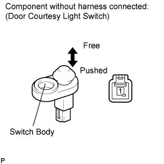
| 4.INSPECT FRONT DOOR COURTESY LIGHT SWITCH ASSEMBLY (DRIVER SIDE) |
Remove the driver side front door courtesy light switch (driver side) (COROLLA_ZRE142 RM000002VPS00OX.html).
Measure the resistance according to the value(s) in the table below.
- Standard Resistance:
Tester Connection
| Switch Condition
| Specified Condition
|
1 - Switch body
| Courtesy switch pushed (Door closed)
| 10 kΩ or higher
|
1 - Switch body
| Courtesy switch free (Door open)
| Below 1 Ω
|
| 5.CHECK HARNESS AND CONNECTOR (FRONT DOOR COURTESY LIGHT SWITCH - MAIN BODY ECU) |
Disconnect the 2A instrument panel junction block connector.
Measure the resistance according to the value(s) in the table below.
- Standard Resistance:
Tester Connection
| Condition
| Specified Condition
|
L3-1 - 2A-21 (DCTY)
| Always
| Below 1 Ω
|
L3-1 - Body ground
| Always
| 10 kΩ or higher
|
| | REPAIR OR REPLACE HARNESS OR CONNECTOR |
|
|
| OK |
|
|
|
| REPLACE MAIN BODY ECU (INSTRUMENT PANEL JUNCTION BLOCK) |
|
| 6.INSPECT UNLOCK WARNING SWITCH ASSEMBLY |
Remove the unlock warning switch assembly (COROLLA_ZRE142 RM0000026TU02HX.html).
Measure the resistance according to the value(s) in the table below.
- Standard Resistance:
Tester Connection
| Switch Condition
| Specified Condition
|
1 - 2
| Switch free (Key removed)
| 10 kΩ or higher
|
1 - 2
| Switch pushed (Key set)
| Below 1 Ω
|
| 7.CHECK HARNESS AND CONNECTOR (UNLOCK WARNING SWITCH - MAIN BODY ECU) |
Disconnect the 2E instrument panel junction block connector.
Measure the resistance according to the value(s) in the table below.
- Standard Resistance:
Tester Connection
| Condition
| Specified Condition
|
E5-1 - 2E-23 (KSW)
| Always
| Below 1 Ω
|
E5-2 - Body ground
| Always
| Below 1 Ω
|
E5-1 - Body ground
| Always
| 10 kΩ or higher
|
| | REPAIR OR REPLACE HARNESS OR CONNECTOR |
|
|
| OK |
|
|
|
| REPLACE MAIN BODY ECU (INSTRUMENT PANEL JUNCTION BLOCK) |
|