Front Axle Hub Installation
INSTALL FRONT AXLE HUB BEARING
INSTALL FRONT DISC BRAKE DUST COVER
INSTALL FRONT AXLE HUB SUB-ASSEMBLY
INSTALL FRONT AXLE HUB HOLE SNAP RING
INSTALL FRONT LOWER BALL JOINT
INSTALL FRONT AXLE ASSEMBLY
INSTALL FRONT LOWER SUSPENSION ARM
INSTALL TIE ROD END SUB-ASSEMBLY
INSTALL FRONT DISC
INSTALL FRONT DISC BRAKE CALIPER ASSEMBLY
TEMPORARILY INSTALL FRONT AXLE HUB NUT
SEPARATE FRONT DISC BRAKE CALIPER ASSEMBLY
REMOVE FRONT DISC
INSPECT FRONT AXLE HUB BEARING LOOSENESS
INSPECT FRONT AXLE HUB RUNOUT
INSTALL FRONT DISC
INSTALL FRONT DISC BRAKE CALIPER ASSEMBLY
CONNECT FRONT SPEED SENSOR (for TMC Made)
CONNECT FRONT SPEED SENSOR (except TMC Made)
INSTALL FRONT AXLE HUB NUT
INSTALL FRONT WHEEL
INSPECT AND ADJUST FRONT WHEEL ALIGNMENT
CHECK FOR SPEED SENSOR SIGNAL
Front Axle Hub -- Installation |
| 1. INSTALL FRONT AXLE HUB BEARING |
Using SST and a press, install a new front axle hub bearing to the steering knuckle.
- SST
- 09950-60020(09951-00720)
09950-70010(09951-07100)
| 2. INSTALL FRONT DISC BRAKE DUST COVER |
Install the disc brake dust cover to the steering knuckle with the 3 bolts.
- Torque:
- 8.3 N*m{85 kgf*cm, 73 in.*lbf}
| 3. INSTALL FRONT AXLE HUB SUB-ASSEMBLY |
Using SST and a press, install the front axle hub sub-assembly.
- SST
- 09608-32010
09950-60010(09951-00600)
09950-70010(09951-07100)
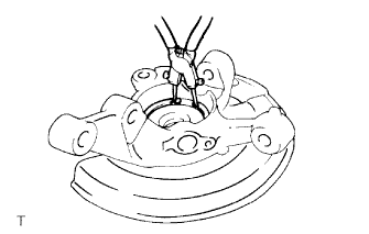
| 4. INSTALL FRONT AXLE HUB HOLE SNAP RING |
Using snap ring pliers, install a new front axle hub hole snap ring.
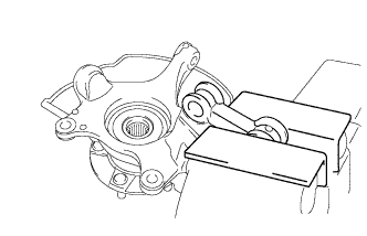
| 5. INSTALL FRONT LOWER BALL JOINT |
Secure the front axle assembly in a vise using aluminum plates.
- NOTICE:
- When using a vise, do not overtighten it.
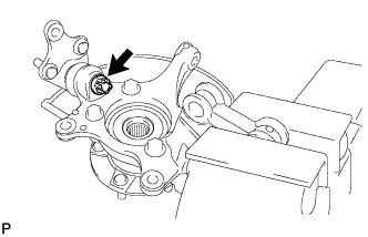
Install the front lower ball joint to the front axle assembly with the nut.
- Torque:
- 2ZR-FE:
- 103 N*m{1050 kgf*cm, 76 ft.*lbf}
- 2AZ-FE:
- 123 N*m{1254 kgf*cm, 91 ft.*lbf}
Install a new cotter pin.
- NOTICE:
- Further tighten the nut up to 60° if the holes for the cotter pin are not aligned.
| 6. INSTALL FRONT AXLE ASSEMBLY |
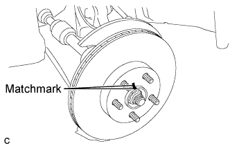
Align the matchmarks and install the front drive shaft assembly to the front axle hub sub-assembly.
Install the front axle assembly to the front shock absorber with the 2 bolts and the 2 nuts.
- Torque:
- 240 N*m{2448 kgf*cm, 176 ft.*lbf}
- NOTICE:
- Be careful not to damage the drive shaft boot or speed sensor rotor.
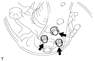
| 7. INSTALL FRONT LOWER SUSPENSION ARM |
Install the front lower suspension arm to the lower ball joint with the bolt and 2 nuts.
- Torque:
- 89 N*m{908 kgf*cm, 66 ft.*lbf}
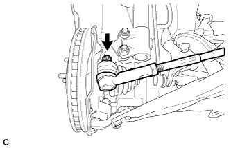
| 8. INSTALL TIE ROD END SUB-ASSEMBLY |
Connect the tie rod end sub-assembly LH to the steering knuckle with the nut.
- Torque:
- 49 N*m{500 kgf*cm, 36 ft.*lbf}
- NOTICE:
- Further tighten the nut up to 60° if the holes for the cotter pin are not aligned.
Install a new cotter pin.
Align the matchmarks of the disc and axle hub, and install the disc.
- NOTICE:
- When replacing the disc with a new one, select the installation position where the front disc has the minimal runout.
| 10. INSTALL FRONT DISC BRAKE CALIPER ASSEMBLY |
Install the front disc brake caliper assembly to the steering knuckle with the 2 bolts.
- Torque:
- 107 N*m{1089 kgf*cm, 79 ft.*lbf}
- NOTICE:
- Do not twist the brake hose when installing the front disc brake caliper assembly.
| 11. TEMPORARILY INSTALL FRONT AXLE HUB NUT |
Clean the threaded parts on the drive shaft and axle hub nut using a non-residue solvent.
- NOTICE:
- Be sure to perform this work when installing a new drive shaft.
- Keep the threaded parts free of oil and foreign objects.
Using a socket wrench (30 mm), while applying the brakes, temporarily install a new axle hub nut.
- Torque:
- 216 N*m{2203 kgf*cm, 158 ft.*lbf}
- HINT:
- Stake the axle hub nut after inspecting for looseness and runout in the following steps.
- Tighten the axle hub nut while the brakes are applied to prevent the front axle from rotating.
| 12. SEPARATE FRONT DISC BRAKE CALIPER ASSEMBLY |
Remove the 2 bolts and separate the front disc brake caliper assembly from the steering knuckle.
- NOTICE:
- Use wire or an equivalent tool to keep the brake caliper from hanging down by the flexible hose.
Put matchmarks on the disc and the axle hub, and remove the front disc.
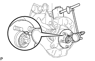
| 14. INSPECT FRONT AXLE HUB BEARING LOOSENESS |
Using a dial indicator, check for looseness near the center of the axle hub.
- Maximum looseness:
- 0.05 mm (0.00196 in.)
- NOTICE:
- Ensure that the dial indicator is set perpendicular to the measurement surface.
If looseness exceeds the maximum, replace the front axle hub bearing.
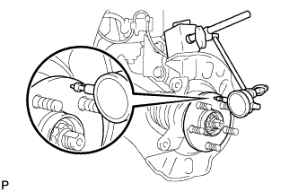
| 15. INSPECT FRONT AXLE HUB RUNOUT |
Using a dial indicator, check for runout on the surface of the axle hub outside the hub bolt.
- Maximum runout:
- 0.03 mm (0.00118 in.)
- NOTICE:
- Ensure that the dial indicator is set perpendicular to the measurement surface.
If runout exceeds the maximum, replace the front axle hub sub-assembly.
Align the matchmarks of the disc and axle hub, and install the disc.
- NOTICE:
- When replacing the disc with a new one, select the installation position where the front disc has the minimal runout.
| 17. INSTALL FRONT DISC BRAKE CALIPER ASSEMBLY |
Install the front disc brake caliper assembly to the steering knuckle with the 2 bolts.
- Torque:
- 107 N*m{1089 kgf*cm, 79 ft.*lbf}
- NOTICE:
- Do not twist the brake hose when installing the front disc brake caliper assembly.
| 18. CONNECT FRONT SPEED SENSOR (for TMC Made) |
Install the front speed sensor and front flexible hose to the front shock absorber with the bolt.
- Torque:
- 29 N*m{296 kgf*cm, 21 ft.*lbf}
- NOTICE:
- Do not twist the front speed sensor when installing it.
- HINT:
- Install the speed sensor harness bracket first, and then the front flexible hose.
| 19. CONNECT FRONT SPEED SENSOR (except TMC Made) |
Install the front speed sensor and front flexible hose to the front shock absorber with the bolt.
- Torque:
- 29 N*m{296 kgf*cm, 21 ft.*lbf}
- NOTICE:
- Do not twist the front speed sensor when installing it.
- HINT:
- Install the speed sensor harness bracket first, and then the front flexible hose.
Install the front speed sensor with the clamp to the front shock absorber.
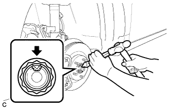
| 20. INSTALL FRONT AXLE HUB NUT |
Using a chisel and hammer, stake the axle hub nut.
- Torque:
- 103 N*m{1050 kgf*cm, 76 ft.*lbf}
| 22. INSPECT AND ADJUST FRONT WHEEL ALIGNMENT |
- HINT:
- COROLLA_ZRE142 RM000001Y3B042X.html
| 23. CHECK FOR SPEED SENSOR SIGNAL |
- HINT:
- COROLLA_ZRE142 RM000000XHT0ATX.html