Theft Deterrent System Unlock Warning Switch Circuit
DESCRIPTION
WIRING DIAGRAM
INSPECTION PROCEDURE
READ VALUE USING TECHSTREAM (UNLOCK WARNING SWITCH ASSEMBLY)
INSPECT UNLOCK WARNING SWITCH ASSEMBLY
CHECK HARNESS AND CONNECTOR (UNLOCK WARNING SWITCH ASSEMBLY - BODY GROUND)
CHECK HARNESS AND CONNECTOR (UNLOCK WARNING SWITCH ASSEMBLY - THEFT WARNING ECU ASSEMBLY)
THEFT DETERRENT SYSTEM - Unlock Warning Switch Circuit |
DESCRIPTION
The key unlock warning switch assembly turns on when the ignition key is inserted into the ignition key cylinder and turns off when the ignition key is removed.The theft warning ECU assembly operates the key confinement prevention function while the key unlock warning switch assembly is on.
WIRING DIAGRAM
INSPECTION PROCEDURE
| 1.READ VALUE USING TECHSTREAM (UNLOCK WARNING SWITCH ASSEMBLY) |
Connect the Techstream to the DLC3.
Turn the ignition switch to ON.
Turn the Techstream on.
Select the item below in the Data List and then read the display on the Techstream.
SecurityTester Display
| Measurement Item/Range
| Normal Condition
| Diagnostic Note
|
Key unlock warning switch
| Unlock warning switch signal / ON or OFF
| ON: Key is inserted into ignition key cylinder
OFF: Key is removed from ignition key cylinder
| -
|
- OK:
- When the key is in the ignition key cylinder, "ON" appears on the screen.
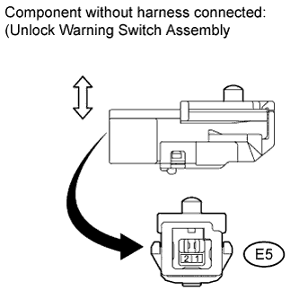
| 2.INSPECT UNLOCK WARNING SWITCH ASSEMBLY |
Remove the unlock warning switch assembly (COROLLA_ZRE142 RM0000026TU02HX.html).
Measure the resistance according to the value(s) in the table below.
- Standard Resistance:
Tester Connection
| Condition
| Specified Condition
|
E5-1 - E5-2
| Free
(Key removed)
| 10 kΩ or higher
|
E5-1 - E5-2
| Pushed
(Key set)
| Below 1 Ω
|
| 3.CHECK HARNESS AND CONNECTOR (UNLOCK WARNING SWITCH ASSEMBLY - BODY GROUND) |
Disconnect the E5 unlock warning switch assembly connector.
Measure the resistance according to the value(s) in the table below.
- Standard Resistance:
Tester Connection
| Condition
| Specified Condition
|
E5-2 - Body ground
| Always
| Below 1 Ω
|
| | REPAIR OR REPLACE HARNESS OR CONNECTOR |
|
|
| 4.CHECK HARNESS AND CONNECTOR (UNLOCK WARNING SWITCH ASSEMBLY - THEFT WARNING ECU ASSEMBLY) |
Disconnect the E110 theft warning ECU assembly connector.
Measure the resistance according to the value(s) in the table below.
- Standard Resistance:
Tester Connection
| Condition
| Specified Condition
|
E5-1 - E110-7 (KSW)
| Always
| Below 1 Ω
|
| | REPAIR OR REPLACE HARNESS OR CONNECTOR |
|
|