Navigation System Speaker Circuit
DESCRIPTION
WIRING DIAGRAM
INSPECTION PROCEDURE
CHECK HARNESS AND CONNECTOR
INSPECT FRONT NO. 1 SPEAKER ASSEMBLY
INSPECT FRONT NO. 2 SPEAKER ASSEMBLY
REPLACE FRONT NO. 2 SPEAKER ASSEMBLY
INSPECT REAR SPEAKER ASSEMBLY
NAVIGATION SYSTEM - Speaker Circuit |
DESCRIPTION
- If there is a short in a speaker circuit, the radio and display receiver assembly detects it and stops output to the speakers.
- Thus sound cannot be heard from the speakers even if there is no malfunction in the radio and display receiver assembly or speakers.
WIRING DIAGRAM
INSPECTION PROCEDURE
| 1.CHECK HARNESS AND CONNECTOR |
Disconnect the connectors from the radio and display receiver assembly and speakers.
Measure the resistance between each of the front No. 2 speaker assemblies and the radio and display receiver assembly to check for an open circuit in the wire harness.
- Standard Resistance:
Tester Connection
| Condition
| Specified Condition
|
E126-1 (FR+) - H4-4 (+)
| Always
| Below 1 Ω
|
E126-5 (FR-) - H4-2 (-)
| Always
| Below 1 Ω
|
E126-2 (FL+) - I4-4 (+)
| Always
| Below 1 Ω
|
E126-6 (FL-) - I4-2 (-)
| Always
| Below 1 Ω
|
Measure the resistance between each of the front No. 1 speaker assemblies and the front No. 2 speaker assemblies to check for an open circuit in the wire harness.
- Standard Resistance:
Tester Connection
| Condition
| Specified Condition
|
H4-3 (TWR+) - H1-1
| Always
| Below 1 Ω
|
H4-1 (TWR-) - H1-2
| Always
| Below 1 Ω
|
I4-3 (TWL+) - I1-1
| Always
| Below 1 Ω
|
I4-1 (TWL-) - I1-2
| Always
| Below 1 Ω
|
Measure the resistance between each of the rear speaker assemblies and the radio and display receiver assembly to check for an open circuit in the wire harness.
- Standard Resistance:
Tester Connection
| Condition
| Specified Condition
|
E127-1 (RR+) - L1-1
| Always
| Below 1 Ω
|
E127-3 (RR-) - L1-2
| Always
| Below 1 Ω
|
E127-2 (RL+) - L2-1
| Always
| Below 1 Ω
|
E127-6 (RL-) - L2-2
| Always
| Below 1 Ω
|
Measure the resistance between the radio and display receiver assembly and body ground to check for a short circuit in the wire harness.
- Standard Resistance:
Tester Connection
| Condition
| Specified Condition
|
E126-1 (FR+) - Body ground
| Always
| 10 kΩ or higher
|
E126-5 (FR-) - Body ground
| Always
| 10 kΩ or higher
|
E126-2 (FL+) - Body ground
| Always
| 10 kΩ or higher
|
E126-6 (FL-) - Body ground
| Always
| 10 kΩ or higher
|
E127-1 (RR+) - Body ground
| Always
| 10 kΩ or higher
|
E127-3 (RR-) - Body ground
| Always
| 10 kΩ or higher
|
E127-2 (RL+) - Body ground
| Always
| 10 kΩ or higher
|
E127-6 (RL-) - Body ground
| Always
| 10 kΩ or higher
|
Measure the resistance between each of the front No. 2 speaker assemblies and body ground to check for a short circuit in the wire harness.
- Standard Resistance:
Tester Connection
| Condition
| Specified Condition
|
H4-3 (TWR+) - Body ground
| Always
| 10 kΩ or higher
|
H4-1 (TWR-) - Body ground
| Always
| 10 kΩ or higher
|
I4-3 (TWL+) - Body ground
| Always
| 10 kΩ or higher
|
I4-1 (TWL-) - Body ground
| Always
| 10 kΩ or higher
|
| | REPAIR OR REPLACE HARNESS OR CONNECTOR |
|
|
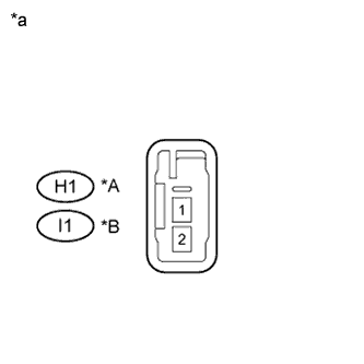
| 2.INSPECT FRONT NO. 1 SPEAKER ASSEMBLY |
Resistance check
Measure the resistance according to the value(s) in the table below.
- Standard Resistance:
Tester Connection
| Condition
| Specified Condition
|
H1-1 - H1-2
| Always
| 3.2 to 4.8 Ω
|
I1-1 - I1-2
| Always
| 3.2 to 4.8 Ω
|
Text in Illustration*A
| for RH
|
*B
| for LH
|
*a
| Component without harness connected
(Front No. 1 Speaker Assembly)
|
| 3.INSPECT FRONT NO. 2 SPEAKER ASSEMBLY |
Resistance check
Measure the resistance according to the value(s) in the table below.
- Standard Resistance:
Tester Connection
| Condition
| Specified Condition
|
H4-2 (-) - H4-4 (+)
| Always
| 10 kΩ or higher
|
H4-1 (TWR-) - H4-2 (-)
| Always
| Below 1 Ω
|
H4-3 (TWR+) - H4-4 (+)
| Always
| Below 1 Ω
|
I4-2 (-) - I4-4 (+)
| Always
| 10 kΩ or higher
|
I4-1 (TWL-) - I4-2 (-)
| Always
| Below 1 Ω
|
I4-3 (TWL+) - I4-4 (+)
| Always
| Below 1 Ω
|
Text in Illustration*A
| for RH
|
*B
| for LH
|
*a
| Component without harness connected
(Front No. 2 Speaker Assembly)
|
| 4.REPLACE FRONT NO. 2 SPEAKER ASSEMBLY |
Check that the malfunction disappears when a known good speaker is installed (COROLLA_ZRE142 RM000002XAP016X.html).
- OK:
- Malfunction disappears.
- HINT:
- Connect all the connectors to the front No. 2 speaker assemblies that were disconnected.
- When there is a possibility that either the right or left front speaker is defective, inspect by interchanging the right one with the left one.
- Perform the above inspection on both LH and RH sides.
| OK |
|
|
|
| END (FRONT NO. 2 SPEAKER ASSEMBLY WAS DEFECTIVE) |
|
| 5.INSPECT REAR SPEAKER ASSEMBLY |
Resistance check
Measure the resistance according to the value(s) in the table below.
- Standard Resistance:
Tester Connection
| Condition
| Specified Condition
|
L1-1 - L1-2
| Always
| 3.2 to 4.8 Ω
|
L2-1 - L2-2
| Always
| 3.2 to 4.8 Ω
|
Text in Illustration*A
| for RH
|
*B
| for LH
|
*a
| Component without harness connected
(Rear Speaker Assembly)
|