Dtc B279A Theft Deterrent System Communication Line High Fixation
DESCRIPTION
WIRING DIAGRAM
INSPECTION PROCEDURE
CHECK DTC OUTPUT
CHECK HARNESS AND CONNECTOR (TRANSPONDER KEY ECU - ECM)
CHECK ECM (INPUT)
REPLACE TRANSPONDER KEY ECU ASSEMBLY
REGISTER KEY
REGISTER ECU COMMUNICATION ID
CHECK DTC OUTPUT
DTC B279A Theft Deterrent System Communication Line High Fixation |
DESCRIPTION
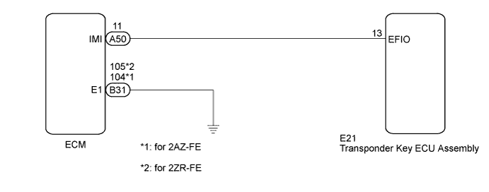
If the communication line (EFIO-IMI) to the transponder key ECU assembly is stuck on HI output, the ECM outputs this DTC.DTC No.
| DTC Detection Condition
| Trouble Area
|
B279A
| Communication line (EFIO-IMI) between ECM and the transponder key ECU assembly is stuck on HI output
| - Wire harness or connector
- Transponder key ECU assembly
- ECM
|
WIRING DIAGRAM
INSPECTION PROCEDURE
- NOTICE:
- If the transponder key ECU assembly is replaced, register the key and ECU communication ID (COROLLA_ZRE142 RM00000120Y02CX.html).
- If the ECM is replaced, register the ECU communication ID (COROLLA_ZRE142 RM00000120Y02CX.html).
Recheck for DTCs (COROLLA_ZRE142 RM000001GV807PX.html).
- HINT:
- If any DTCs other than DTC B279A are output, troubleshoot those DTCs first.
- Result:
Result
| Proceed to
|
DTC B279A and other DTCs reoutput
| A
|
DTC B279A reoutput
| B
|
| 2.CHECK HARNESS AND CONNECTOR (TRANSPONDER KEY ECU - ECM) |
Disconnect the transponder key ECU assembly connector.
Disconnect the ECM connector.
Measure the resistance and voltage according to the value(s) in the table below.
- Standard Resistance:
Tester Connection
| Condition
| Specified Condition
|
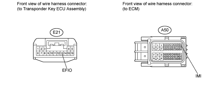
E21-13 (EFIO) - A50-11 (IMI)
| Always
| Below 1 Ω
|
E21-13 (EFIO) - Body ground
| Always
| 10 kΩ or higher
|
- Standard Voltage:
Tester Connection
| Condition
| Specified Condition
|
E21-13 (EFIO) - Body ground
| Always
| Below 1 V
|
| | REPAIR OR REPLACE HARNESS OR CONNECTOR |
|
|
Reconnect the transponder key ECU assembly connector.
Reconnect the ECM connector.
Measure the waveform.
- Waveform 1 (Reference):
Item
| Content
|
Terminal No. (Symbols)
| A50-11 (IMI) - B31-104 (E1)*1
A50-11 (IMI) - B31-105 (E1)*2
|
Tool Setting
| 2 V/DIV., 1 s./DIV.
|
Condition
| Ignition switch ON
|
- *1: for 2AZ-FE
- *2: for 2ZR-FE
- Result:
Result
| Proceed to
|
OK (for 2ZR-FE)
| A
|
OK (for 2AZ-FE)
| B
|
NG
| C
|
| 4.REPLACE TRANSPONDER KEY ECU ASSEMBLY |
Replace the transponder key ECU assembly (COROLLA_ZRE142 RM000003G05004X.html).
Register the key (COROLLA_ZRE142 RM00000120Y02CX.html).
| 6.REGISTER ECU COMMUNICATION ID |
Register the ECU communication ID (COROLLA_ZRE142 RM00000120Y02CX.html).
Clear the DTCs (COROLLA_ZRE142 RM000001GV807PX.html).
Recheck for DTCs.
- OK:
- B279A is not reoutput.
- Result:
Result
| Proceed to
|
NG (for 2ZR-FE)
| A
|
NG (for 2ZA-FE)
| B
|
OK
| C
|
| C |
|
|
|
| END (TRANSPONDER KEY ECU IS DEFECTIVE) |
|