DESCRIPTION
WIRING DIAGRAM
INSPECTION PROCEDURE
INSPECT ECU TERMINAL VOLTAGE (INPUT VOLTAGE)
INSPECT COMBINATION METER (OUTPUT VOLTAGE)
INSPECT SKID CONTROL ECU (INPUT WAVEFORM)
CHECK HARNESS AND CONNECTOR (COMBINATION METER - SKID CONTROL ECU)
CHECK HARNESS AND CONNECTOR (COMBINATION METER - NO. 4 JUNCTION BLOCK)
CHECK HARNESS AND CONNECTOR (NO. 4 JUNCTION BLOCK)
SYSTEM CHECK
CHECK HARNESS AND CONNECTOR (TIRE PRESSURE WARNING ECU CIRCUIT)
CHECK HARNESS AND CONNECTOR (ECM CIRCUIT)
CHECK HARNESS AND CONNECTOR (NAVIGATION RECEIVER ASSEMBLY CIRCUIT)
CHECK HARNESS AND CONNECTOR (RADIO RECEIVER CIRCUIT, RADIO AND DISPLAY RECEIVER CIRCUIT)
CHECK HARNESS AND CONNECTOR
INSPECT RADIO RECEIVER (CHECK FOR A SHORT)
INSPECT TIRE PRESSURE WARNING ECU (CHECK FOR A SHORT)
INSPECT RADIO AND DISPLAY RECEIVER (CHECK FOR A SHORT)
CHECK HARNESS AND CONNECTOR (INSTRUMENT PANEL JUNCTION BLOCK)
SYSTEM CHECK
CHECK HARNESS AND CONNECTOR (ECM CIRCUIT)
CHECK HARNESS AND CONNECTOR (SLIDING ROOF CONTROL ECU CIRCUIT)
METER / GAUGE SYSTEM - Speed Signal Circuit |
DESCRIPTION
The combination meter receives the vehicle speed signal from this circuit. The wheel speed sensors produce an output that varies according to the vehicle speed. The wheel speed sensor output is received by the skid control ECU which uses this information to create the vehicle speed sensor signal*. The vehicle speed sensor signal consists of pulses sent to the combination meter from the skid control ECU. To create this signal, 12 V is output from IG2 which is behind a resistor in the combination meter. This voltage is sent to the skid control ECU. The pulse signal is created by switching the transistor in the skid control ECU on and off, making the voltage on the wire drop to 0 V. A similar system is used for the output of this signal from the combination meter via terminal +S. A voltage of 12 V or 5 V is applied to terminal +S from each ECU or relay that is connected to this terminal. The transistor in the combination meter is controlled by the signal from the skid control ECU. When this transistor is turned on, this transistor makes the voltage supplied by the various ECUs (via their respective internal resistors) drop to 0 V. Each ECU connected to terminal +S of the combination meter controls its respective system based on the pulse signal.- *: This vehicle speed sensor signal is created by the skid control ECU. There is no actual component that is referred to as the vehicle speed sensor. In addition, for some other systems, vehicle speed information may be exchanged using CAN communication.
- HINT:
- This circuit is used for the systems connected to terminal +S. This signal is not used for combination meter operation. Combination meter components such as the speedometer operate using data received via CAN communication.
WIRING DIAGRAM
INSPECTION PROCEDURE
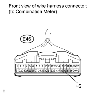
| 1.INSPECT ECU TERMINAL VOLTAGE (INPUT VOLTAGE) |
Disconnect the E46 connector.
Measure the voltage according to the value(s) in the table below.
- Standard Voltage:
Tester Connection
| Condition
| Specified Condition
|
E46-36 (+S) - Body ground
| Ignition switch ON
| 4.5 to 14 V
|
- HINT:
- If any of the ECUs specified in the wiring diagram supplied power to the combination meter, the combination meter will output a waveform.
- Result:
Result
| Proceed to
|
OK
| A
|
NG (for TMC Made)
| B
|
NG (except for TMC Made)
| C
|
| 2.INSPECT COMBINATION METER (OUTPUT VOLTAGE) |
Reconnect the E46 connector.
Disconnect the A51*1 or A66*2 connector.
Measure the voltage according to the value(s) in the table below.
- Standard Voltage:
Tester Connection
| Condition
| Specified Condition
|
A51-22 (SP1)*1 - Body ground
| Ignition switch ON
| 11 to 14 V
|
A66-11 (SP1)*2 - Body ground
| Ignition switch ON
| 11 to 14 V
|
- *1: w/o VSC
- *2: w/ VSC
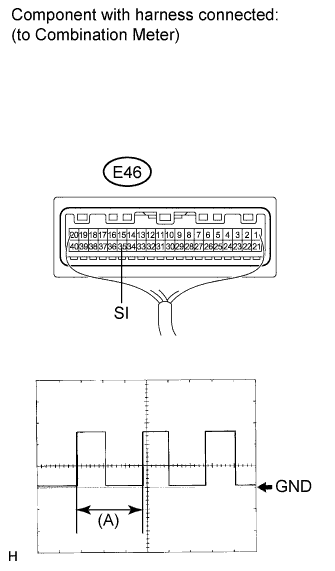
| 3.INSPECT SKID CONTROL ECU (INPUT WAVEFORM) |
Check the input waveform.
Reconnect the A51*1 or A66*2 connector.
- *1: w/o VSC
- *2: w/ VSC
Remove the combination meter with the connector(s) still connected.
Connect the oscilloscope to terminals E46-35 (SI) and body ground.
Turn the ignition switch to ON.
Turn the wheel slowly.
Check the signal waveform according to the condition(s) in the table below.
Item
| Condition
|
Tool setting
| 5 V/DIV., 20 ms./DIV.
|
Vehicle condition
| Driving at approximately 12 mph (20 km/h)
|
- OK:
- The waveform is displayed as shown in the illustration.
- HINT:
- When the system is functioning normally, one wheel revolution generates 4 pulses. As the vehicle speed increases, the width indicated by (A) in the illustration narrows.
- Result:
Result
| Proceed to
|
OK
| A
|
NG (w/o VSC)
| B
|
NG (w/ VSC)
| C
|
| 4.CHECK HARNESS AND CONNECTOR (COMBINATION METER - SKID CONTROL ECU) |
Disconnect the E46 connector.
Measure the resistance according to the value(s) in the table below.
- Standard Resistance:
Tester Connection
| Condition
| Specified Condition
|
A51-22 (SP1)*1 - E46-35 (SI)
| Always
| Below 1 Ω
|
A51-22 (SP1)*1 - Body ground
| Always
| 10 kΩ or higher
|
A66-11 (SP1)*2 - E46-35 (SI)
| Always
| Below 1 Ω
|
A66-11 (SP1)*2 - Body ground
| Always
| 10 kΩ or higher
|
- *1: w/o VSC
- *2: w/ VSC
| | REPAIR OR REPLACE HARNESS OR CONNECTOR |
|
|
| 5.CHECK HARNESS AND CONNECTOR (COMBINATION METER - NO. 4 JUNCTION BLOCK) |
Disconnect the 4C connector.
Measure the resistance according to the value(s) in the table below.
- Standard Resistance:
Tester Connection
| Condition
| Specified Condition
|
E46-36 (+S) - 4C-13
| Always
| Below 1 Ω
|
4C-13 - Body ground
| Always
| 10 kΩ or higher
|
| | REPAIR OR REPLACE HARNESS OR CONNECTOR |
|
|
| 6.CHECK HARNESS AND CONNECTOR (NO. 4 JUNCTION BLOCK) |
Inspect for a short in the circuit that is connected to the combination meter shown in the wiring diagram.
- HINT:
- If voltage is not present, the circuit (ECU) was possibly the malfunctioning circuit. This is the circuit that will be diagnosed by following the A step that follows.
Disconnect 4A connector.
Measure the voltage according to the value(s) in the table below.
- Standard Voltage:
Tester Connection
| Condition
| Specified Condition
|
4A-87*1 - Body ground
| Ignition switch ON
| 4.5 to 14 V
|
4A-38 - Body ground
| Ignition switch ON
| 4.5 to 14 V
|
4A-37 - Body ground
| Ignition switch ON
| 4.5 to 14 V
|
- *1: w/ Tire Pressure Warning System
Reconnect 4A connector.
Disconnect 4C connector.
Measure the voltage according to the value(s) in the table below.
- Standard Voltage:
Tester Connection
| Condition
| Specified Condition
|
4C-1*2 - Body ground
| Ignition switch ON
| 4.5 to 14 V
|
- *2: for Navigation Receiver Type
- Result:
Result
| Proceed to
|
Voltage is not present in one circuit.
| A
|
Voltage is present in all the circuits.
| B
|
| | REPAIR OR REPLACE HARNESS OR CONNECTOR (NO. 4 JUNCTION BLOCK) |
|
|
Select the circuit that did not present the voltage in the step 6.
- Result:
Tester Connection
| System that uses the circuit
| Proceed to
|
4A-87*1 - Body ground
| Tire pressure warning System
| A
|
4A-38 - Body ground
| SFI System
| B
|
4C-1*2 - Body ground
| Navigation System
| C
|
4A-37 - Body ground
| Audio/visual System*2
| D
|
Audio/visual System*3
| E
|
- *1: w/ Tire Pressure Warning System
- *2: for Navigation Receiver Type
- *3: for Radio Receiver Type
- *4: for Radio and Display Receiver Type
| 8.CHECK HARNESS AND CONNECTOR (TIRE PRESSURE WARNING ECU CIRCUIT) |
Reconnect the E94 connector.
Measure the resistance according to the value(s) in the table below.
- Standard Resistance:
Tester Connection
| Condition
| Specified Condition
|
E94-2 (SPD) - Body ground
| Always
| 10 kΩ or higher
|
| | REPAIR OR REPLACE HARNESS OR CONNECTOR |
|
|
| 9.CHECK HARNESS AND CONNECTOR (ECM CIRCUIT) |
Reconnect the A50 connector.
Measure the resistance according to the value(s) in the table below.
- Standard Resistance:
Tester Connection
| Condition
| Specified Condition
|
A50-38 (SPD) - Body ground
| Always
| 10 kΩ or higher
|
| | REPAIR OR REPLACE HARNESS OR CONNECTOR |
|
|
| 10.CHECK HARNESS AND CONNECTOR (NAVIGATION RECEIVER ASSEMBLY CIRCUIT) |
- HINT:
- If the vehicle does not equipped with the navigation system, proceed to the next step.
Reconnect the E117 connector.
Measure the resistance according to the value(s) in the table below.
- Standard Resistance:
Tester Connection
| Condition
| Specified Condition
|
E117-3 (SPD) - Body ground
| Always
| 10 kΩ or higher
|
| | REPAIR OR REPLACE HARNESS OR CONNECTOR |
|
|
| 11.CHECK HARNESS AND CONNECTOR (RADIO RECEIVER CIRCUIT, RADIO AND DISPLAY RECEIVER CIRCUIT) |
Reconnect the E26*1 or E114*2 connector.
Measure the resistance according to the value(s) in the table below.
- Standard Resistance:
Tester Connection
| Condition
| Specified Condition
|
E26-3 (SPD)*1 - Body ground
| Always
| 10 kΩ or higher
|
E114-17 (SPD)*2 - Body ground
| Always
| 10 kΩ or higher
|
E129-17 (SPD)*3 - Body ground
| Always
| 10 kΩ or higher
|
- *1: for Radio Receiver Type (w/o USB Audio System)
- *2: for Radio Receiver Type (w/ USB Audio System)
- *3: for Radio and Display Type
- Result:
Result
| Proceed to
|
OK (for Radio Receiver Type)
| A
|
OK (for Radio and Display Type)
| B
|
NG
| C
|
| |
|
| | REPAIR OR REPLACE HARNESS OR CONNECTOR |
|
|
| 12.CHECK HARNESS AND CONNECTOR |
Inspect for a short in the circuit that is connected to the combination meter shown in the wiring diagram.
- HINT:
- If voltage is not present, the circuit (ECU) was possibly the malfunctioning circuit.
Disconnect the E26*1 or E114*2, E94*3, E129*4 and 2E connectors.
- *1: for Radio Receiver Type (w/o USB Audio System)
- *2: for Radio Receiver Type (w/ USB Audio System)
- *3: w/ Tire Pressure Warning System
- *4: for Radio and Display Type
Measure the resistance according to the value(s) in the table below.
- Standard Resistance:
Tester Connection
| Condition
| Specified Condition
|
E46-36 (+S) - Body ground
| Always
| 10 kΩ or higher
|
| | REPAIR OR REPLACE HARNESS OR CONNECTOR |
|
|
| 13.INSPECT RADIO RECEIVER (CHECK FOR A SHORT) |
- HINT:
- If the vehicle does not equipped with the radio receiver, proceed to the next step.
Reconnect the E26*1 or E114*2 connector.
Measure the voltage according to the value(s) in the table below.
- Standard Voltage:
Tester Connection
| Condition
| Specified Condition
|
E26-3 (SPD)*1 - Body ground
| Ignition switch ON
| 4.5 to 14 V
|
E114-17 (SPD)*2 - Body ground
| Ignition switch ON
| 4.5 to 14 V
|
- *1: w/o USB Audio System
- *2: w/ USB Audio System
| 14.INSPECT TIRE PRESSURE WARNING ECU (CHECK FOR A SHORT) |
- HINT:
- If the vehicle does not equipped with the tire pressure warning system, proceed to the next step.
Reconnect the E94 connector.
Measure the voltage according to the value(s) in the table below.
- Standard Voltage:
Tester Connection
| Condition
| Specified Condition
|
E94-2 (SPD)* - Body ground
| Ignition switch ON
| 4.5 to 14 V
|
- *: w/ Tire Pressure Warning System
| 15.INSPECT RADIO AND DISPLAY RECEIVER (CHECK FOR A SHORT) |
- HINT:
- If the vehicle does not equipped with the radio and display receiver, proceed to the next step.
Reconnect the E129 connector.
Measure the voltage according to the value(s) in the table below.
- Standard Voltage:
Tester Connection
| Condition
| Specified Condition
|
E129-17 (SPD) - Body ground
| Ignition switch ON
| 4.5 to 14 V
|
| 16.CHECK HARNESS AND CONNECTOR (INSTRUMENT PANEL JUNCTION BLOCK) |
Inspect for a short in the circuit that is connected to the combination meter shown in the wiring diagram.
- HINT:
- If voltage is not present, the circuit (ECU) was possibly the malfunctioning circuit. This is the circuit that will be diagnosed by following the A step that follows.
Disconnect 2C, 2D, and 2E connector.
Measure the voltage according to the value(s) in the table below.
- Standard Voltage:
Tester Connection
| Condition
| Specified Condition
|
2C-8*2 - Body ground
| Ignition switch ON
| 4.5 to 14 V
|
2D-8 - Body ground
| Ignition switch ON
| 4.5 to 14 V
|
2E-1*1 - Body ground
| Ignition switch ON
| 4.5 to 14 V
|
- *1: w/ Smart Key System
- *2: w/ Sliding Roof
- Result:
Result
| Proceed to
|
Voltage is not present in one circuit.
| A
|
Voltage is present in all the circuits.
| B
|
| | REPAIR OR REPLACE HARNESS OR CONNECTOR (INSTRUMENT PANEL JUNCTION BLOCK) |
|
|
Select the circuit that did not present the voltage in the step 16.
- Result:
Tester Connection
| System that uses the circuit
| Proceed to
|
2D-8 - Body ground
| SFI System
| A
|
2C-8*2 - Body ground
| Sliding Roof Control System
| B
|
2E-1*1 - Body ground
| Smart Key System
| C
|
- *1: w/ Smart Key System
- *2: w/ Sliding Roof
| 18.CHECK HARNESS AND CONNECTOR (ECM CIRCUIT) |
Disconnect the A50 connector.
Measure the resistance according to the value(s) in the table below.
- Standard Resistance:
Tester Connection
| Condition
| Specified Condition
|
A50-8 (SPD)*1 - Body ground
| Always
| 10 kΩ or higher
|
A50-38 (SPD)*2 - Body ground
| Always
| 10 kΩ or higher
|
- Result:
Result
| Proceed to
|
OK (for 2AZ-FE)
| A
|
OK (for 2ZR-FE)
| B
|
NG
| C
|
- *1: for 2AZ-FE
- *2: for 2ZR-FE
| |
|
| | REPAIR OR REPLACE HARNESS OR CONNECTOR |
|
|
| 19.CHECK HARNESS AND CONNECTOR (SLIDING ROOF CONTROL ECU CIRCUIT) |
Disconnect the O11 connector.
Measure the resistance according to the value(s) in the table below.
- Standard Resistance:
Tester Connection
| Condition
| Specified Condition
|
O11-8 (SPD) - Body ground
| Always
| 10 kΩ or higher
|
| | REPAIR OR REPLACE HARNESS OR CONNECTOR |
|
|