Sfi System Fuel Pump Control Circuit
DESCRIPTION
WIRING DIAGRAM
INSPECTION PROCEDURE
PERFORM ACTIVE TEST USING TECHSTREAM (OPERATE C/OPN RELAY)
INSPECT FUSE (IGN FUSE)
INSPECT INSTRUMENT PANEL JUNCTION BLOCK (C/OPN RELAY)
CHECK HARNESS AND CONNECTOR (C/OPN RELAY - ECM)
CHECK HARNESS AND CONNECTOR (C/OPN RELAY - INTEGRATION RELAY (EFI MAIN RELAY))
CHECK HARNESS AND CONNECTOR (C/OPN RELAY - FUEL PUMP)
CHECK HARNESS AND CONNECTOR (FUEL PUMP - BODY GROUND)
INSPECT FUEL PUMP ASSEMBLY
CHECK ECM POWER SOURCE CIRCUIT
SFI SYSTEM - Fuel Pump Control Circuit |
DESCRIPTION
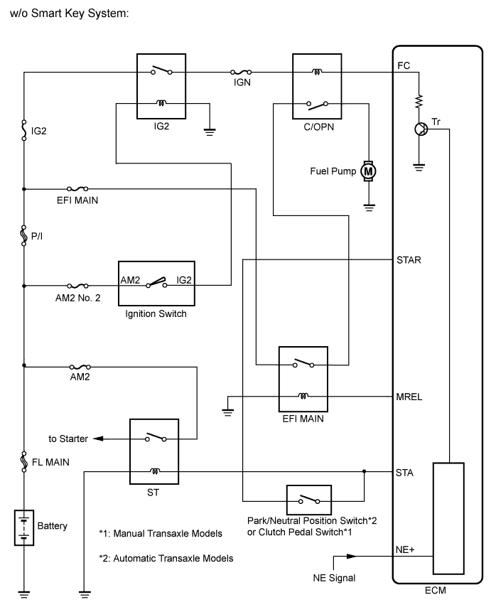
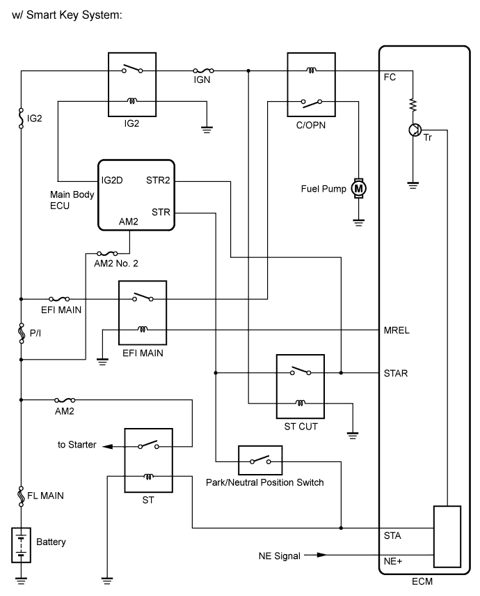
In the diagram below, when the engine is cranked, the starter relay drive signal output from the STAR terminal of the ECM is input to the STA terminal of the ECM, and NE signal generated by the crankshaft position sensor is also input to the NE+ terminal.When the STA signal and NE signal are input to the ECM, Tr is turned on, current flows to the coil of the circuit opening (C/OPN) relay, the relay switches on, power is supplied to the fuel pump and the fuel pump operates.While the NE signal is generated (engine running), the ECM keeps Tr on (circuit opening relay on) and the fuel pump also keeps operating.
WIRING DIAGRAM
INSPECTION PROCEDURE
| 1.PERFORM ACTIVE TEST USING TECHSTREAM (OPERATE C/OPN RELAY) |
Connect the Techstream to the DLC3.
Turn the ignition to switch to ON.
Turn the Techstream on.
Enter the following menus: Powertrain / Engine and ECT / Active Test / Control the Fuel Pump / Speed.
Check whether the fuel pump operation sound occurs when performing the Active Test on the Techstream.
- OK:
- Fuel pump operating sound occurs.
| 2.INSPECT FUSE (IGN FUSE) |
Remove the IGN fuse from the instrument panel junction block.
Measure the resistance according to the value(s) in the table below.
- Standard Resistance:
Tester Connection
| Condition
| Specified Condition
|
IGN fuse
| Always
| Below 1 Ω
|
Reinstall the IGN fuse.
| | CHECK FOR SHORTS IN ALL HARNESSES AND CONNECTORS CONNECTED TO FUSE AND REPLACE FUSE |
|
|
| 3.INSPECT INSTRUMENT PANEL JUNCTION BLOCK (C/OPN RELAY) |
Disconnect the instrument panel junction block connector.
Measure the resistance according to the value(s) in the table below.
- Standard Resistance:
Tester Connection
| Condition
| Specified Condition
|
2A-8 - 2B-11
| Always
| 10 kΩ or higher
|
Apply battery voltage to terminals 2B-10 and 2F-4
| Below 1 Ω
|
Reconnect the instrument panel junction block connector.
| | REPLACE INSTRUMENT PANEL JUNCTION BLOCK (C/OPN RELAY) |
|
|
| 4.CHECK HARNESS AND CONNECTOR (C/OPN RELAY - ECM) |
Disconnect the ECM connector.
Disconnect the instrument panel junction block connector.
Measure the resistance according to the value(s) in the table below.
- Standard Resistance (Check for Open):
Tester Connection
| Condition
| Specified Condition
|
2B-10 - A50-19 (FC)
| Always
| Below 1 Ω
|
- Standard Resistance (Check for Short):
Tester Connection
| Condition
| Specified Condition
|
2B-10 or A50-19 (FC) - Body ground
| Always
| 10 kΩ or higher
|
Reconnect the ECM connector.
Reconnect the instrument panel junction block connector.
| | REPAIR OR REPLACE HARNESS OR CONNECTOR (C/OPN RELAY - ECM) |
|
|
| 5.CHECK HARNESS AND CONNECTOR (C/OPN RELAY - INTEGRATION RELAY (EFI MAIN RELAY)) |
Remove the integration relay from engine room junction block.
Disconnect the integration relay connector.
Disconnect the instrument panel junction block connector.
Measure the resistance according to the value(s) in the table below.
- Standard Resistance (Check for Open):
Tester Connection
| Condition
| Specified Condition
|
2B-11 - 1B-4
| Always
| Below 1 Ω
|
- Standard Resistance (Check for Short):
Tester Connection
| Condition
| Specified Condition
|
2B-11 or 1B-4 - Body ground
| Always
| 10 kΩ or higher
|
Reconnect the instrument panel junction block connector.
Reconnect the integration relay connector.
Reinstall the integration relay.
| | REPAIR OR REPLACE HARNESS OR CONNECTOR (C/OPN RELAY - INTEGRATION RELAY (EFI MAIN RELAY)) |
|
|
| 6.CHECK HARNESS AND CONNECTOR (C/OPN RELAY - FUEL PUMP) |
Disconnect the fuel pump connector.
Disconnect the instrument panel junction block connector.
Measure the resistance according to the value(s) in the table below.
- Standard Resistance (Check for Open):
Tester Connection
| Condition
| Specified Condition
|
2A-8 - L17-4
| Always
| Below 1 Ω
|
- Standard Resistance (Check for Short):
Tester Connection
| Condition
| Specified Condition
|
2A-8 or L17-4 - Body ground
| Always
| 10 kΩ or higher
|
Reconnect the fuel pump connector.
Reconnect the instrument panel junction block connector.
| | REPAIR OR REPLACE HARNESS OR CONNECTOR (C/OPN RELAY - FUEL PUMP) |
|
|
| 7.CHECK HARNESS AND CONNECTOR (FUEL PUMP - BODY GROUND) |
Disconnect the fuel pump connector.
Measure the resistance according to the value(s) in the table below.
- Standard Resistance:
Tester Connection
| Condition
| Specified Condition
|
L17-5 - Body ground
| Always
| Below 1 Ω
|
Reconnect the fuel pump connector.
| | REPAIR OR REPLACE HARNESS OR CONNECTOR (FUEL PUMP - BODY GROUND) |
|
|
| 8.INSPECT FUEL PUMP ASSEMBLY |
Inspect the fuel pump assembly (COROLLA_ZRE142 RM0000022XV036X.html).
| 9.CHECK ECM POWER SOURCE CIRCUIT |
Check the ECM power source circuit (COROLLA_ZRE142 RM0000027690AZX.html).
| | REPAIR OR REPLACE ECM POWER SOURCE CIRCUIT |
|
|