Lighting System Lvl Terminal Circuit
DESCRIPTION
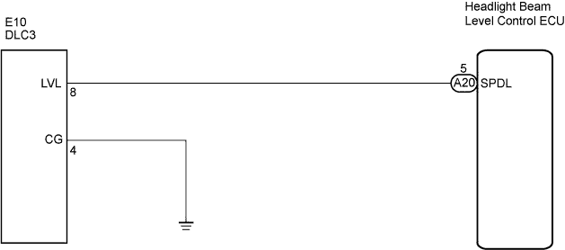
WIRING DIAGRAM
INSPECTION PROCEDURE
CHECK HARNESS AND CONNECTOR (DLC3 - HEADLIGHT BEAM LEVEL CONTROL ECU)
CHECK HARNESS AND CONNECTOR (DLC3 - BODY GROUND)
LIGHTING SYSTEM - LVL Terminal Circuit |
DESCRIPTION
- By connecting terminals LVL and CG of the DLC3, the headlight beam level control ECU performs the following:
- Initializes the height control sensor signal.
- Performs the operation check of the headlight leveling motor.
WIRING DIAGRAM
INSPECTION PROCEDURE
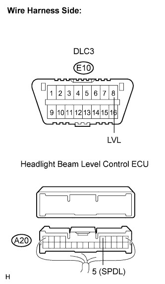
| 1.CHECK HARNESS AND CONNECTOR (DLC3 - HEADLIGHT BEAM LEVEL CONTROL ECU) |
Disconnect the A20 headlight beam level control ECU connector.
Measure the resistance according to the value(s) in the table below.
- Standard resistance:
Tester Connection
| Condition
| Specified Condition
|
A20-5 (SPDL) - E10-8 (LVL)
| Always
| Below 1 Ω
|
A20-5 (SPDL) - Body ground
| Always
| 10 kΩ or higher
|
| | REPAIR OR REPLACE HARNESS OR CONNECTOR |
|
|
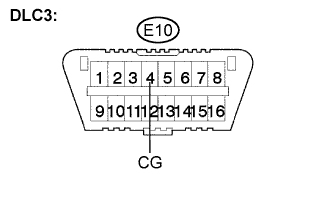
| 2.CHECK HARNESS AND CONNECTOR (DLC3 - BODY GROUND) |
Measure the resistance according to the value(s) in the table below.
- Standard resistance:
Tester Connection
| Condition
| Specified Condition
|
E10-4 (CG) - Body ground
| Always
| Below 1 Ω
|
| | REPAIR OR REPLACE HARNESS OR CONNECTOR |
|
|
| OK |
|
|
|
| PROCEED TO NEXT CIRCUIT INSPECTION SHOWN IN PROBLEM SYMPTOMS TABLE |
|