2AD-FHV problems
Black Smoke Emitted
Inspection procedure
NOTICE:
- After replacing the ECM, the new ECM needs registration and initialization.
- After replacing a supply pump, the ECM needs initialization.
- After replacing a injector, the ECM needs registration.
HINT:
Specified values in the following troubleshooting flowchart are for reference only. Variations in the Data List values may occur depending on the measuring conditions or the vehicle's age. Do not assume the vehicle to be normal when the Data List outputs standard values. There may be concealed factors of the malfunction.
| 1.CHECK OUTPUT DTC (RELATED TO ENGINE) |
-
Connect the intelligent tester to the DLC3.
-
Turn the ignition switch on (IG) and turn the tester ON.
-
Enter the following menus: Powertrain / Engine and ECT / DTC.
-
Read the DTCs.
Result:Display (DTC Output) Proceed to No output A DTCs related to the engine B
|
|
||||
| A | |
| 2.READ VALUE OF INJECTOR ASSEMBLY (INJECTION VOLUME AND INJECTION FEED BACK VAL #1 TO #4) |
-
Connect the intelligent tester to the DLC3.
-
Start the engine and turn the tester ON.
-
Enter the following menus: Powertrain / Engine and ECT / Data List.
-
Select the following menu items in order and read the values.
- Injection Volume
- Injection Feedback Val #1, #2, #3, and #4
Standard value:
Item Engine Speed* Reference Value Injection Volume Idling (No engine load) 3.9 to 7.0 mm3 Injection Feedback Val #1 Idling (No engine load) -3.0 to 3.0 mm3 Injection Feedback Val #2 Idling (No engine load) -3.0 to 3.0 mm3 Injection Feedback Val #3 Idling (No engine load) -3.0 to 3.0 mm3 Injection Feedback Val #4 Idling (No engine load) -3.0 to 3.0 mm3 HINT:
*: If no idling conditions are specified, the shift lever should be in the neutral position, and the A/C switch and all accessory switches should be OFF.
|
|
||||
| OK | |
| 3.PERFORM ENGINE RPM ACCELERATION |
HINT:
If the exhaust gas contains excessive black smoke, perform the following operations:
-
Accelerate the engine speed to the maximum rpm with no load 20 times.
-
Check the volume of black smoke in the exhaust gas.
Result:Result Proceed to Black smoke is not present OK Black smoke remains in the exhaust gas NG HINT:
Soot deposits in the exhaust system may cause excessive black smoke.
|
|
||||
| NG | |
| 4.CHECK AIR INTAKE SYSTEM AND EXHAUST SYSTEM |
-
Inspect the engine condition.
|
|
||||
| OK | |
| 5.READ VALUE USING INTELLIGENT TESTER (EGR LIFT POSITION) |
-
Connect the intelligent tester to the DLC3.
-
Turn the ignition switch on (IG) and turn the tester ON.
-
Enter the following menus: Powertrain / Engine and ECT / Data List / EGR Lift Position.
-
Read the value.
Standard value:
0 to 60% idling after engine warmed up and vehicle is under normal atmospheric pressure.
HINT:
In the chart above, "Idling" means that the engine should be idled under the following conditions:
- Idle the engine, turn the A/C switch OFF and move the shift lever to N.
- After the engine is warmed up, the engine should have no load.
|
|
||||
| OK | |
| 6.CHECK TURBOCHARGING PRESSURE |
-
Check the turbocharger pressure.
Standard pressure:
48 to 53 kPa (0.49 to 0.54 kgf/cm2, 6.9 to 7.7 psi)
|
|
||||
| OK | |
| 7.PERFORM ACTIVE TEST BY FUEL PRESSURE SENSOR AND INJECTOR ASSEMBLY |
-
Connect the intelligent tester to the DLC3.
-
Start the engine and turn the tester ON.
-
Enter the following menus: Powertrain / Engine and ECT / Data List.
-
Select the following menu items in order and read the values.
- Fuel Pressure
- Injection Volume
- Main Injection
- Pilot 2 Injection
- Injection Feedback Val #1, #2, #3, and #4
Reference:
Item Engine Speed* Reference Value Fuel Pressure Idling 32 to 43 MPa Fuel Pressure 2,000 rpm (no engine load) 47 to 53 MPa Fuel Pressure 3,000 rpm (no engine load) 60 to 66 MPa Injection Volume Idling 3.9 to 7.0 mm3 Injection Volume 2,000 rpm (no engine load) 5.6 to 9.1 mm3 Injection Volume 3,000 rpm (no engine load) 7.9 to 11.4 mm3 Main Injection Idling 170 to 370 ?s Pilot 2 Injection Idling 140 to 200 ?s Injection Feedback Val #1 Idling -3.0 to 3.0 mm3 Injection Feedback Val #2 Idling -3.0 to 3.0 mm3 Injection Feedback Val #3 Idling -3.0 to 3.0 mm3 Injection Feedback Val #4 Idling -3.0 to 3.0 mm3 HINT:
If no idling conditions are specified, the shift lever should be in the neutral position, and the A/C switch and all accessory switches should be OFF.
Result:Result Proceed to Within reference value A One of Injection Feedback Val #1 to #4 is not within reference value B Other result C
|
|
||||
|
|
||||
| A | |
| 8.CHECK CYLINDER COMPRESSION PRESSURE |
-
Check the cylinder compression pressure.
Standard pressure:
2,700 kPa (27.5 kgf/cm2, 392 psi)
Minimum pressure:
2,200 kPa (22.4 kgf/cm2, 319 psi)
Difference between each cylinder:
500 kPa (5.1 kgf/cm2, 73 psi)
|
|
||||
| OK | |
| 9.CHECK WIRE HARNESS (INJECTOR - EDU) |
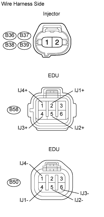
-
Disconnect the B36, B37, B38, and B39 injector connectors.
-
Disconnect the B50 and B58 EDU connectors.
-
Measure the resistance of the wire harness side connectors.
Standard resistance:
Tester Connection Specified Condition B36-1 - B58-2 (IJ1+) Below 1 ? B37-1 - B58-5 (IJ2+) Below 1 ? B38-1 - B58-4 (IJ3+) Below 1 ? B39-1 - B58-1 (IJ4+) Below 1 ? B36-2 - B50-4 (IJ1-) Below 1 ? B37-2 - B50-5 (IJ2-) Below 1 ? B38-2 - B50-6 (IJ3-) Below 1 ? B39-2 - B50-1 (IJ4-) Below 1 ? B36-1 or B58-2 (IJ1+) - Body ground 10 k? or higher B37-1 or B58-5 (IJ2+) - Body ground 10 k? or higher B38-1 or B58-4 (IJ3+) - Body ground 10 k? or higher B39-1 or B58-1 (IJ4+) - Body ground 10 k? or higher B36-2 or B50-4 (IJ1-) - Body ground 10 k? or higher B37-2 or B50-5 (IJ2-) - Body ground 10 k? or higher B38-2 or B50-6 (IJ3-) - Body ground 10 k? or higher B39-2 or B50-1 (IJ4-) - Body ground 10 k? or higher -
Reconnect the injector connectors.
-
Reconnect the EDU connectors.
|
|
||||
| OK | |
| 10.PERFORM ACTIVE TEST BY INTELLIGENT TESTER (CONTROL THE CYLINDER FUEL CUT) |
-
Connect the intelligent tester to the DLC3.
-
Start the engine and turn the tester ON.
-
Enter the following menus: Powertrain / Engine and ECT / Active Test / Control the Cylinder #1, #2, #3, and #4 Fuel Cut.
-
Check the engine idling condition while the fuel injection of each cylinder is cut using the tester.
Result:Engine Idling Condition Proceed to Becomes unstable A Does not change B HINT:
Replace the injector mounted on the cylinder that causes no significant idle speed change.
|
|
||||
| A | |
|
| 11.READ VALUE USING INTELLIGENT TESTER (ENGINE COOLANT TEMPERATURE) |
-
Connect the intelligent tester to the DLC3.
-
Turn the ignition switch on (IG) and turn the tester ON.
-
Enter the following menus: Powertrain / Engine and ECT / Data List / Coolant Temp.
-
Read the value.
Standard value:
Between 75 and 95°C (167 and 203°F) with warm engine.
|
|
||||
| OK | |
| 12.READ VALUE OF MANIFOLD ABSOLUTE PRESSURE SENSOR |
-
Connect the intelligent tester to the DLC3.
-
Turn the ignition switch on (IG) and turn the tester ON.
-
Enter the following menus: Powertrain / Engine and ECT / Data List / MAP and Atmosphere Pressure.
-
Read the value.
Standard value:
Condition MAP Value No pressure applied Same as atmospheric pressure Vacuum applied Becomes vacuum Pressure applied Becomes pressurized
|
|
||||
| OK | |
| 13.READ VALUE USING INTELLIGENT TESTER (ENGINE SPEED) |
-
Connect the intelligent tester to the DLC3.
-
Turn the ignition switch on (IG) and turn the tester ON.
-
Enter the following menus: Powertrain / Engine and ECT / Data List / Engine Speed.
-
Read the value.
Standard value:
Between 750 to 1,000 rpm with warm engine (A/C switch OFF).
|
|
||||
| OK | |
| 14.READ VALUE USING INTELLIGENT TESTER (ACCEL POSITION 1 AND 2) |
-
Connect the intelligent tester to the DLC3.
-
Turn the ignition switch on (IG) and turn the tester ON.
-
Enter the following menus: Powertrain / Engine and ECT / Data List / Coolant Temp.
-
Read the value.
Standard voltage:
Accelerator Pedal Accelerator Pedal Condition Specified Condition Accel Position 1 Released 0.6 to 1.0 V Accel Position 1 Depressed 3.4 to 3.8 V Accel Position 2 Released 1.4 to 1.8 V Accel Position 2 Depressed 4.2 to 4.6 V HINT:
In the chart above, "Idling" means that the engine should be idled under the following conditions:
- Idle the engine, turn the A/C switch OFF and move the shift lever to N.
- After the engine is warmed up, the engine should have no load.
|
|
||||
| OK | |
| 15.READ VALUE USING INTELLIGENT TESTER (INTAKE AIR TEMPERATURE) |
-
Connect the intelligent tester to the DLC3.
-
Turn the ignition switch on (IG) and turn the tester ON.
-
Enter the following menus: Powertrain / Engine and ECT / Data List / Inlet Air.
-
Read the value.
OK:
Same as air temperature near to intake manifold.
HINT:
In the chart above, "Idling" means that the engine should be idled under the following conditions:
- Idle the engine, turn the A/C switch OFF and move the shift lever to N.
- After the engine is warmed up, the engine should have no load.
|
|
||||
| OK | |
| 16.READ VALUE USING INTELLIGENT TESTER (FUEL PRESSURE) |
-
Connect the intelligent tester to the DLC3.
-
Turn the ignition switch on (IG) and turn the tester ON.
-
Enter the following menus: Powertrain / Engine and ECT / Data List / Coolant Temp.
-
Read the value.
Standard value:
32 to 43 MPa engine idling.
|
|
||||
| OK | |
|
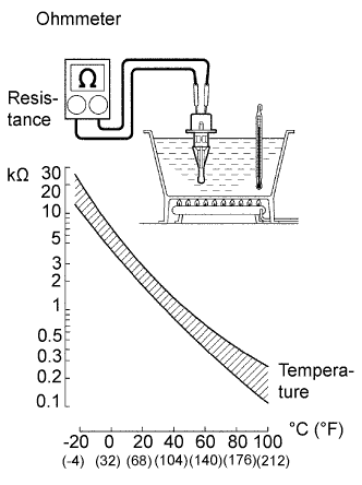
| 17.INSPECT ENGINE COOLANT TEMPERATURE SENSOR |
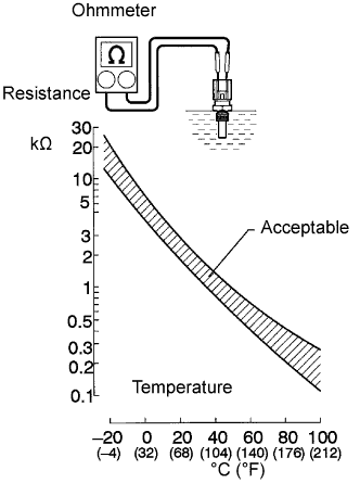
-
Disconnect the engine coolant temperature sensor.
-
Measure the resistance of the sensor.
Standard resistance:
Connection Specified Condition 20°C (68°F) 2.32 to 2.59 k? 80°C (176°F) 0.310 to 0.326 k? NOTICE:
When checking the ECT sensor in water, keep the terminals dry. After the check, wipe the sensor dry.
HINT:
Alternative procedure: Connect an ohmmeter to the installed ECT sensor and read the resistance. Use an infrared thermometer to measure the engine temperature in the immediate vicinity of the sensor. Compare these values against the resistance/ temperature graph. Change the engine temperature (warm up or cool down) and repeat the test.
-
Reconnect the engine coolant temperature sensor.
|
|
||||
| OK | |
|
| 18.CHECK WIRE HARNESS (MANIFOLD ABSOLUTE PRESSURE SENSOR - ECM) |
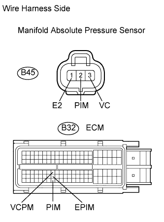
-
Disconnect the B45 manifold absolute pressure sensor connector.
-
Disconnect the B32 ECM connector.
-
Measure the resistance of the wire harness side connectors.
Standard resistance:
Tester Connection Specified Condition B45-2 (PIM) - B32-117 (PIM) Below 1 ? B45-3 (VC) - B32-71 (VCPM) Below 1 ? B45-1 (E) - B32-94 (EPIM) Below 1 ? B45-2 (PIM) or B32-117 (PIM) - Body ground 10 k? or higher B45-3 (VC) or B32-71 (VCPM) - Body ground 10 k? or higher B45-1 (E) or B32-94 (EPIM) - Body ground 10 k? or higher -
Reconnect the manifold absolute pressure sensor connector.
-
Reconnect the ECM connector.
|
|
||||
| OK | |
|
| 19.INSPECT CRANKSHAFT POSITION SENSOR |
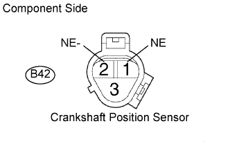
-
Disconnect the B42 crankshaft position sensor connector.
-
Measure the resistance of the sensor.
Standard resistance:
Tester Connection Condition Specified Condition B42-1 (NE) - B42-2 (NE-) Cold 835 to 1,400 ? B42-1 (NE) - B42-2 (NE-) Hot 1,060 to 1,645 ? HINT:
In the table above, the terms "Cold" and "Hot" refer to the temperature of the coils in the sensor. "Cold" means approximately -10 to 50°C (14 to 122°F). "Hot" means approximately 50 to 100°C (122 to 212°F).
-
Reconnect the crankshaft position sensor connector.
|
|
||||
| OK | |
|
| 20.CHECK WIRE HARNESS (ACCELERATOR PEDAL POSITION SENSOR - ECM) |
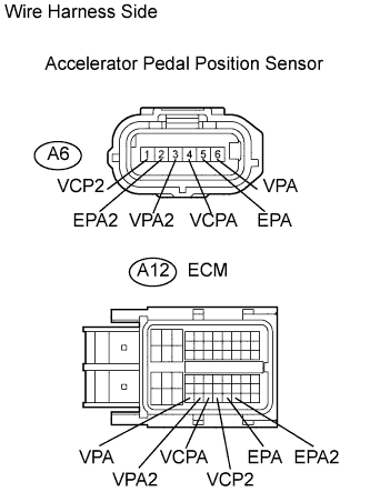
-
Disconnect the A6 sensor connector.
-
Disconnect the A12 ECM connector.
-
Measure the resistance of the wire harness side connectors.
Standard resistance:
Tester Connection Specified Condition A6-1 (VCP2) - A12-56 (VCP2) Below 1 ? A6-2 (EPA2) - A12-58 (EPA2) Below 1 ? A6-3 (VPA2) - A12-54 (VPA2) Below 1 ? A6-4 (VCPA) - A12-55 (VCPA) Below 1 ? A6-5 (EPA) - A12-57 (EPA) Below 1 ? A6-6 (VPA) - A12-53 (VPA) Below 1 ? A6-1 (VCP2) or A12-56 (VCP2) - Body ground 10 k? or higher A6-2 (EPA2) or A12-58 (EPA2) - Body ground 10 k? or higher A6-3 (VPA2) or A12-54 (VPA2) - Body ground 10 k? or higher A6-4 (VCPA) or A12-55 (VCPA) - Body ground 10 k? or higher A6-5 (EPA) or A12-57 (EPA) - Body ground 10 k? or higher A6-6 (VPA) or A12-53 (VPA) - Body ground 10 k? or higher -
Reconnect the sensor connector.
-
Reconnect the ECM connector.
|
|
||||
| OK | |
|
| 21.INSPECT INTAKE AIR TEMPERATURE SENSOR |
-
Remove the intake air temperature sensor.
-
Measure the resistance of the sensor.
Standard resistance:
Tester Connection Condition Specified Condition 1 - 2 20°C (68°F) 2.21 to 2.69 k? NOTICE:
When checking the sensor in water, keep the terminals dry. After the check, wipe the sensor dry.
-
Reconnect the intake air temperature sensor.
|
|
||||
| OK | |
|
| 22.INSPECT COMMON RAIL ASSEMBLY (FUEL PRESSURE SENSOR) |
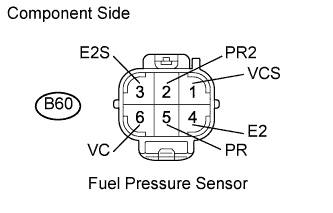
-
Disconnect the B60 fuel pressure sensor connector.
-
Measure the resistance of each terminal of the fuel pressure sensor.
Standard resistance:
Tester Connection Specified Condition B60-5 (PR) - B60-4 (E2) 16.4 k? or less B60-2 (PR2) - B60-3 (E2S) 16.4 k? or less B60-5 (PR) - B60-6 (VC) 3 k? or less B60-2 (PR2) - B60-1 (VC2) 3 k? or less -
Reconnect the fuel pressure sensor connector.
|
|
||||
| OK | |
| 23.CHECK WIRE HARNESS (FUEL PRESSURE SENSOR - ECM) |
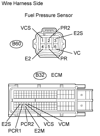
-
Disconnect the B60 fuel pressure sensor connector.
-
Disconnect the B32 ECM connector.
-
Measure the resistance of the wire harness side connectors.
Standard resistance:
Tester Connection Specified Condition B60-5 (PR) - B32-67 (PCR1) Below 1 ? B60-2 (PR2) - B32-114 (PCR2) Below 1 ? B60-1 (VCS) - B32-68 (VCS) Below 1 ? B60-6 (VC) - B32-69 (VCM) Below 1 ? B60-4 (E2) - B32-91 (E2M) Below 1 ? B60-3 (E2S) - B32-66 (E2S) Below 1 ? B60-5 (PR) or B32-67 (PCR1) - Body ground 10 k? or higher B60-2 (PR2) or B32-114 (PCR2) - Body ground 10 k? or higher B60-1 (VCS) or B32-68 (VCS) - Body ground 10 k? or higher B60-6 (VC) or B32-69 (VCM) - Body ground 10 k? or higher B60-4 (E2) or B32-91 (E2M) - Body ground 10 k? or higher B60-3 (E2S) or B32-66 (E2S) - Body ground 10 k? or higher -
Reconnect the fuel pressure sensor connector.
-
Reconnect the ECM connector.
|
|
||||
| OK | |
| 24.REPLACE ECM |
-
Replace the ECM.
NOTICE:
After replacing the ECM, the new ECM needs registration and initialization.
-
Check the volume of black smoke in the exhaust gas.
OK:
Black smoke is not present.
|
|
||||
| OK | |
|