DISCONNECT CABLE FROM NEGATIVE BATTERY TERMINAL
REMOVE RADIATOR SUPPORT OPENING COVER
REMOVE FRONT WHEEL RH
REMOVE NO. 1 ENGINE UNDER COVER
REMOVE FRONT FENDER APRON RH
REMOVE NO. 1 ENGINE COVER
DRAIN ENGINE OIL
REMOVE FRONT EXHAUST PIPE
REMOVE FRONT SUSPENSION MEMBER REINFORCEMENT RH
REMOVE FAN AND GENERATOR V BELT
REMOVE GENERATOR ASSEMBLY
REMOVE RADIATOR RESERVOIR
REMOVE ENGINE MOUNTING INSULATOR RH
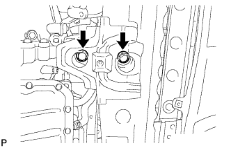
REMOVE ENGINE MOUNTING INSULATOR FR
REMOVE IDLER PULLEY
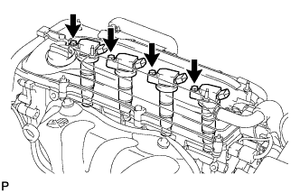
REMOVE IGNITION COIL ASSEMBLY
REMOVE CYLINDER HEAD COVER SUB-ASSEMBLY
REMOVE OIL PAN SUB-ASSEMBLY
SET NO. 1 CYLINDER TO TDC/COMPRESSION
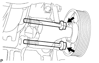
REMOVE CRANKSHAFT PULLEY
REMOVE NO. 1 CHAIN TENSIONER ASSEMBLY
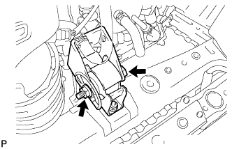
REMOVE ENGINE MOUNTING BRACKET RH
REMOVE V-RIBBED BELT TENSIONER ASSEMBLY
REMOVE CRANKSHAFT POSITION SENSOR
REMOVE TIMING CHAIN COVER SUB-ASSEMBLY
REMOVE NO. 1 CRANKSHAFT POSITION SENSOR PLATE
REMOVE TIMING CHAIN GUIDE
REMOVE CHAIN TENSIONER SLIPPER
REMOVE NO. 1 CHAIN VIBRATION DAMPER
REMOVE CHAIN SUB-ASSEMBLY
REMOVE CRANKSHAFT TIMING SPROCKET
REMOVE NO. 2 CHAIN SUB-ASSEMBLY
| 1. DISCONNECT CABLE FROM NEGATIVE BATTERY TERMINAL |
- ПРЕДОСТЕРЕЖЕНИЕ:
- Wait at least 90 seconds after disconnecting the cable from the negative (-) battery terminal to prevent airbag and seat belt pretensioner activation.
| 2. REMOVE RADIATOR SUPPORT OPENING COVER |
| 4. REMOVE NO. 1 ENGINE UNDER COVER |
| 5. REMOVE FRONT FENDER APRON RH |
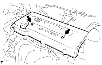
| 6. REMOVE NO. 1 ENGINE COVER |
Remove the 2 nuts and cover.
Remove the oil filler cap.
Remove the oil drain plug and drain the oil into a container.
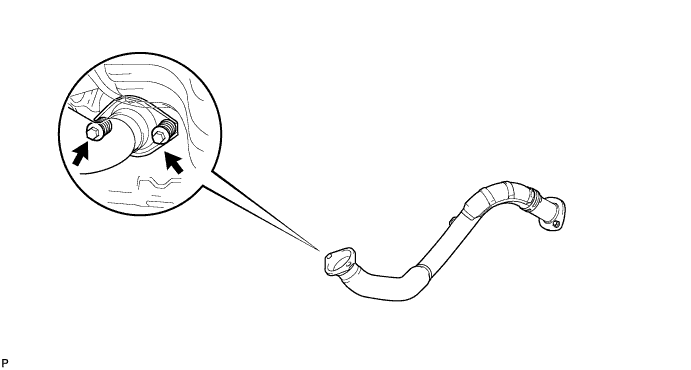
| 8. REMOVE FRONT EXHAUST PIPE |
Remove the 2 bolts, 2 compression springs and front exhaust pipe.
Remove the gasket from the exhaust manifold.
| 9. REMOVE FRONT SUSPENSION MEMBER REINFORCEMENT RH |
Remove the 4 bolts and reinforcement RH.
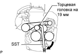
| 10. REMOVE FAN AND GENERATOR V BELT |
Using SST and 19 mm socket wrench, loosen the V-ribbed belt tensioner arm clockwise, then remove the fan and generator V belt.
- Специальный инструмент (SST):
- 09216-42010
- ПРИМЕЧАНИЕ:
- Be sure to connect SST and the tools so that they are in line during use.
- When retracting the tensioner, turn it clockwise slowly for 3 seconds or more. Do not apply force rapidly.
- After the tensioner is fully retracted, do not apply force any more than necessary.
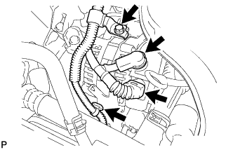
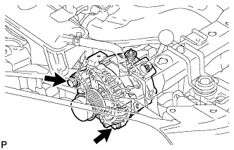
| 11. REMOVE GENERATOR ASSEMBLY |
Disconnect the generator connector.
Remove the terminal cap.
Remove the nut and disconnect the generator wire.
Remove the bolt and wire harness clamp bracket.
Remove the wire harness clamps.
Remove the 2 bolts and generator.
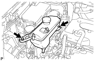
| 12. REMOVE RADIATOR RESERVOIR |
Remove the 2 bolts and radiator reservoir with the No. 1 and No. 2 water by-pass hose.
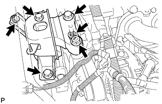
| 13. REMOVE ENGINE MOUNTING INSULATOR RH |
Remove the bolt of the wire harness protector.
Disconnect the 2 clamps of the engine wire.
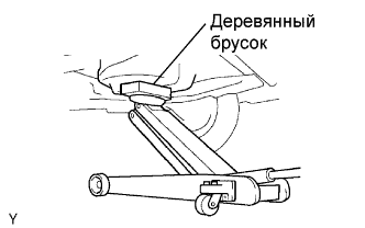
Place a transmission jack underneath the engine, then put a wooden block on the jack.
Remove the 4 bolts, 2 nuts and engine mounting insulator RH.
- ПРИМЕЧАНИЕ:
- Do not apply excessive force to the return tube when removing the engine mounting insulator RH.
- УКАЗАНИЕ:
- Keep clearance by lowering the engine using the transmission jack when removing the engine mounting insulator FR.
| 14. REMOVE ENGINE MOUNTING INSULATOR FR |
Remove the through bolt and nut.
Remove the 2 bolts and engine mounting insulator FR.
- УКАЗАНИЕ:
- Keep clearance by lowering the engine using the transmission jack when removing the engine mounting insulator FR.
Loosen the 2 bolts and remove the idler bracket with the 2 bolts.
| 16. REMOVE IGNITION COIL ASSEMBLY |
Disconnect the 4 ignition coil connectors.
Remove the 4 bolts and 4 ignition coils.
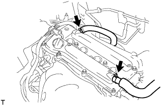
| 17. REMOVE CYLINDER HEAD COVER SUB-ASSEMBLY |
Disconnect the 2 ventilation hoses from the cylinder head cover.
Remove the 2 bolts and disconnect the 2 engine wires.
Remove the 8 bolts, 2 nuts and cylinder head cover.
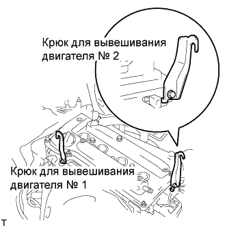
| 18. REMOVE OIL PAN SUB-ASSEMBLY |
Install the No. 1 and No. 2 engine hangers with the bolts.
- Момент затяжки:
- 38 Н*м{387 кгс*см, 28 фунт-сила-футов}
Part No.Item
| Part No.
|
No. 1 engine hanger
| 12281-28010
|
No. 2 engine hanger
| 12282-28010
|
Bolt
| 91512-61020
|
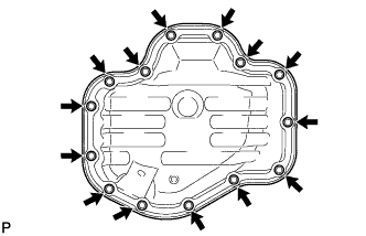
Attach the sling device to the engine hangers and chain block.
Remove the 12 bolts and 2 nuts.
Insert the blade of SST between the crankcase, chain cover and oil pan, then cut off the applied sealer and remove the oil pan.
- Специальный инструмент (SST):
- 09032-00100
- ПРИМЕЧАНИЕ:
- Be careful not to damage the contact surface of the crankcase, chain cover and oil pan.
| 19. SET NO. 1 CYLINDER TO TDC/COMPRESSION |
Turn the crankshaft pulley until its groove and the timing mark "0" of the timing chain cover are aligned.
Check that each timing mark of the camshaft timing gear and sprocket is aligned with each timing mark located on the No. 1 and No. 2 bearing caps as shown in the illustration.
If not, turn the crankshaft by 1 revolution (360°) to align the timing marks as above.
| 20. REMOVE CRANKSHAFT PULLEY |
Using SST, fix the pulley in place and loosen the pulley bolt.
- Специальный инструмент (SST):
- 09213-54015(91651-60855)
09330-00021
Remove the crankshaft pulley.
- УКАЗАНИЕ:
- If necessary, remove the pulley with SST and the pulley bolt.
- Специальный инструмент (SST):
- 09950-50013(09951-05010,09952-05010,09953-05020,09954-05021)
09950-40011(09957-04010)
| 21. REMOVE NO. 1 CHAIN TENSIONER ASSEMBLY |
Remove the 2 nuts, chain tensioner and gasket.
- ПРИМЕЧАНИЕ:
- Do not turn the crankshaft without the chain tensioner.
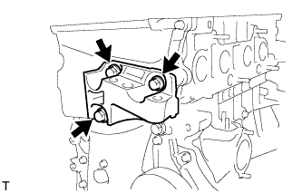
| 22. REMOVE ENGINE MOUNTING BRACKET RH |
Remove the 3 bolts and engine mounting bracket RH.
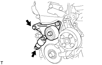
| 23. REMOVE V-RIBBED BELT TENSIONER ASSEMBLY |
Lift the engine upward using the transmission jack.
- ПРИМЕЧАНИЕ:
- Do not lift the engine more than necessary.
Remove the bolt, nut and V-ribbed belt tensioner.
| 24. REMOVE CRANKSHAFT POSITION SENSOR |
Disconnect the sensor connector.
Remove the connector clamp.
Remove the wire harness from the wire harness clamp bracket.
Remove the wire harness clamp.
Remove the bolt and sensor.
| 25. REMOVE TIMING CHAIN COVER SUB-ASSEMBLY |
Using an E10 "torx" socket, remove the stud bolt for the V-ribbed belt tensioner.
Remove the 12 bolts and 2 nuts.
Remove the timing chain cover by prying the portions between the timing chain cover, cylinder head and cylinder block with a screwdriver.
- ПРИМЕЧАНИЕ:
- Be careful not to damage the contact surfaces of the timing chain cover, cylinder head and cylinder block.
| 26. REMOVE NO. 1 CRANKSHAFT POSITION SENSOR PLATE |
| 27. REMOVE TIMING CHAIN GUIDE |
Remove the bolt and timing chain guide.
| 28. REMOVE CHAIN TENSIONER SLIPPER |
Remove the bolt and chain tensioner slipper.
| 29. REMOVE NO. 1 CHAIN VIBRATION DAMPER |
Remove the 2 bolts and chain vibration damper.
| 30. REMOVE CHAIN SUB-ASSEMBLY |
| 31. REMOVE CRANKSHAFT TIMING SPROCKET |
| 32. REMOVE NO. 2 CHAIN SUB-ASSEMBLY |
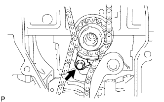
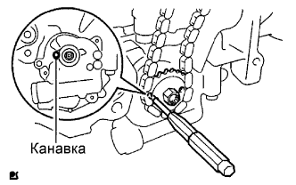
Turn the crankshaft by 90°counterclockwise to align the adjusting hole of the oil pump drive shaft sprocket with the groove of the oil pump.
Insert a 4 mm diameter bar into the adjusting hole of the oil pump drive shaft sprocket to lock the gear in position, and then remove the nut.
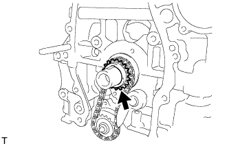
Remove the bolt, chain tensioner plate and spring.
Remove the oil pump drive sprocket, oil pump drive shaft sprocket and No. 2 chain.