Dtc P0724 Brake Switch B Circuit High
DESCRIPTION
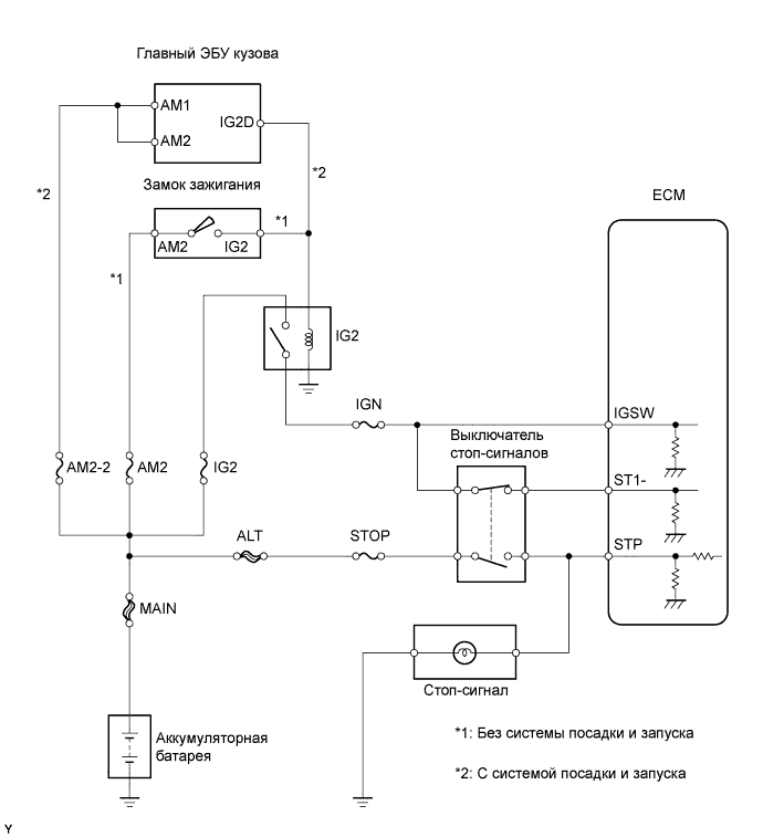
WIRING DIAGRAM
INSPECTION PROCEDURE
READ VALUE OF INTELLIGENT TESTER (STOP LIGHT SWITCH)
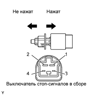
INSPECT STOP LIGHT SWITCH ASSEMBLY
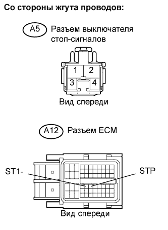
CHECK HARNESS AND CONNECTOR (STOP LIGHT SWITCH - ECM)
DTC P0724 Brake Switch "B" Circuit High |
DESCRIPTION
The purpose of this circuit is to prevent the engine from stalling when brakes are suddenly applied while driving in lock-up condition. When the brake pedal is depressed, this switch sends a signals to the ECM. Then the ECM cancels the operation of the lock-up clutch while braking is in progress.DTC No.
| DTC Detection Condition
| Trouble Area
|
P0724
| Stop light switch remains ON even when vehicle repeats 5 cycles of STOP (less than 1.86 mph [3 km/h]) and GO (18.65 mph [30 km/h] or more)
(2 trip detection logic)
| - Short in stop light switch signal circuit
- Stop light switch
- ECM
|
WIRING DIAGRAM
INSPECTION PROCEDURE
- УКАЗАНИЕ:
- Read freeze frame data using the intelligent tester. Freeze frame data records the engine condition when malfunctions are detected. When troubleshooting, freeze frame data can help determine if the vehicle was moving or stationary, if the engine was warmed up or not, if the air-fuel ratio was lean or rich, and other data from the time the malfunction occurred.
| 1.READ VALUE OF INTELLIGENT TESTER (STOP LIGHT SWITCH) |
Connect the intelligent tester to the DLC3.
Turn the ignition switch on (IG) and turn the tester ON.
Select the following menu items: Powertrain / Engine and ECT / Data List / Stop Light Switch.
Read the values displayed on the tester.
- OK:
Item
| Measurement Item / Range (display)
| Normal Condition
|
Stop Light Switch
| Stop light switch status:
ON or OFF
| - ON: Brake Pedal is depressed
- OFF: Brake Pedal is released
|
| | CHECK FOR INTERMITTENT PROBLEMS |
|
|
| 2.INSPECT STOP LIGHT SWITCH ASSEMBLY |
Remove the stop light switch assembly.
Measure the resistance.
- Standard resistance:
Tester Connection
| Switch Position
| Specified Condition
|
1 - 2
| Switch pin not pushed
| Below 1 Ω
|
Switch pin pushed
| 10 kΩ or higher
|
3 - 4
| Switch pin not pushed
| 10 kΩ or higher
|
Switch pin pushed
| Below 1 Ω
|
Reinstall the stop light switch assembly.
| | REPLACE STOP LIGHT SWITCH ASSEMBLY |
|
|
| 3.CHECK HARNESS AND CONNECTOR (STOP LIGHT SWITCH - ECM) |
Disconnect the A12 ECM connector.
Disconnect the A5 stop light switch connector.
Measure the resistance between the wire harness side connectors.
- Standard resistance (Check for open):
Tester Connection
| Specified Condition
|
STP (A12-36) - Stop light switch (A5-1)
| Below 1 Ω
|
ST1- (A12-35) - Stop light switch (A5-4)
|
- Standard resistance (Check for short):
Tester Connection
| Specified Condition
|
STP (A12-36) or Stop light switch (A5-1) - Body ground
| 10 kΩ or higher
|
ST1- (A12-35) or Stop light switch (A5-4) - Body ground
|
Reconnect the ECM connector.
Reconnect the stop light switch connector.
| | REPAIR OR REPLACE HARNESS OR CONNECTOR |
|
|