Engine Unit -- Reassembly |
| 1. INSTALL PISTON WITH PIN SUB-ASSEMBLY |
Assemble the piston and connecting rod.
Using a screwdriver, install a new snap ring at one end of the piston pin hole.
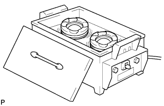
Gradually heat the piston to approximately 80 to 90°C (176 to 194°F).
Coat the piston pin with engine oil.
Align the front marks of the piston and connecting rod, and push in the piston pin with your thumb.
- УКАЗАНИЕ:
- The piston and pin are a matched set.
Check the fitting condition between the piston and piston pin by trying to move the piston back and forth on the piston pin.
Using a screwdriver, install a new snap ring at the other end of the piston pin hole.


 |
| 2. INSTALL PISTON RING SET |
Install the oil ring expander by hand.
 |
Using a piston ring expander, install the oil ring rail.
 |
Using a piston ring expander, install the 2 compression rings so that the painted marks are positioned as shown in the illustration.
- УКАЗАНИЕ:
- Install the No. 1 compression ring with the code mark (1T) facing upward.
- Install the No. 2 compression ring with the code mark (2FTE) facing upward.
 |
Position the piston rings so that the ring ends are as shown in the illustration.
- ПРИМЕЧАНИЕ:
- Do not align the ring ends.
 |
| 3. INSTALL CYLINDER BLOCK WATER DRAIN COCK SUB-ASSEMBLY |
Apply adhesive around the drain cock.
- Seal packing:
- Toyota genuine seal packing 1282B, three bond 1282B or equivalent.
 |
Install the cylinder block water drain cock.
Temporarily install the cock.
- Момент затяжки:
- 20 Н*м{204 кгс*см, 15 фунт-сила-футов}
Within one full rotation, tighten the cock to the angle shown the illustration.
- Момент затяжки:
- 80 Н*м{816 кгс*см, 59 фунт-сила-футов}or lower
- ПРИМЕЧАНИЕ:
- Do not loosen the cock to adjust it. If an adjustment is necessary, remove the cock and reinstall it.

| 4. INSTALL NO. 1 CRANKSHAFT POSITION SENSOR PLATE |
Install the sensor plate by fitting the straight pin of the crankshaft into the hole on the sensor plate.
 |
Using a T30 "torx" socket wrench, install the 3 bolts.
- Момент затяжки:
- 10.5 Н*м{107 кгс*см, 8 фунт-сила-футов}
- ПРИМЕЧАНИЕ:
- Make sure confirm that the sensor plate is not slanted.
| 5. INSTALL OIL REFLECTOR PLATE |
Using a 5 mm hexagon wrench, install the oil reflector plates.
- Момент затяжки:
- 9.0 Н*м{92 кгс*см, 80 фунт-сила-дюймов}
 |
| 6. INSTALL NO. 1 OIL NOZZLE SUB-ASSEMBLY |
Using a 5 mm hexagon wrench, install the oil nozzles.
- Момент затяжки:
- 9.0 Н*м{92 кгс*см, 80 фунт-сила-дюймов}
 |
| 7. INSTALL NO. 2 CRANKSHAFT BEARING |
- ПРИМЕЧАНИЕ:
- Do not apply engine oil to the bearing's contact area and backside.
Clean the main journal, and the both surfaces of the bearing.
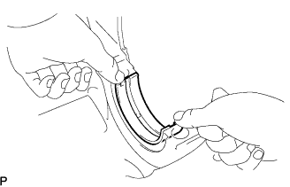
Align the bearing claw with the claw groove of the crankshaft bearing cap, and push in the 5 lower bearings.
 |
| 8. INSTALL CRANKSHAFT BEARING |
- ПРИМЕЧАНИЕ:
- Do not apply engine oil to the bearing's contact area and backside.
Clean the main journal, and the both surfaces of the bearing.
Align the bearing claw groove of the cylinder block, and push in the 5 upper bearings.
 |
| 9. INSTALL CRANKSHAFT UPPER THRUST WASHER |
Apply engine oil to the crankshaft bearings, then place the crankshaft on the cylinder block.
Install the 2 thrust washers to the No. 4 journal position of the cylinder block.
 |
Push the crankshaft toward the front (rear) side.
Check the 2 thrust washers with the oil grooves facing outward.
| 10. INSTALL CRANKSHAFT |
Apply seal packing in a continuous bead as shown in the illustration.
- Seal packing:
- Toyota genuine seal packing block, three bond 1207B or equivalent
- Seal diameter:
- 2.0 to 4.0 mm (0.078 to 0.157 in.)
- ПРИМЕЧАНИЕ:
- Remove any oil from the contact surface.
- Install the crankcase within 3 minutes after applying seal packing.
- Do not start the engine for at least 4 hours after installing.
- Do not overlap seal packing in area ● in the illustration.
- Do not apply seal packing in groove C.
 |
Apply engine oil to the crankshaft No. 2 bearings, then place the crankshaft bearing cap on the cylinder block.
Install the crankshaft bearing cap bolts.
- УКАЗАНИЕ:
- The main bearing cap bolts are tightened in 2 progressive steps.
Step 1
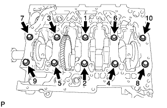
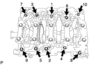
Install and uniformly tighten the 10 main bearing cap bolts in the sequence shown in the illustration.
- Момент затяжки:
- 60 Н*м{612 кгс*см, 44 фунт-сила-футов}
- УКАЗАНИЕ:
- If any of the main bearing cap bolts does not meet the torque specification, replace the main bearing cap bolt.
 |
Step 2
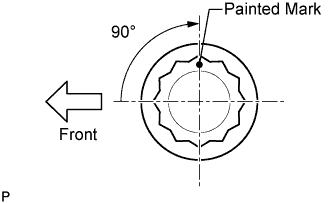
Mark the front of the bearing cap bolts with paint.
Retighten the bearing cap bolts by 90° as shown.
Check that the painted mark is now at a 90° angle to the front.
 |
Check that the crankshaft turns smoothly.
Install and uniformly tighten the 10 bolts in several passes in the sequence shown.
- Момент затяжки:
- 18 Н*м{184 кгс*см, 13 фунт-сила-футов}
 |
| 11. INSTALL CONNECTING ROD BEARING |
Install the bearings in the connecting rod and connecting rod cap.
 |
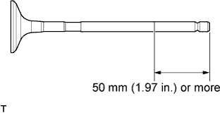
Using vernier calipers, measure the distance between the bearing cap's and bearing's edge.
- Dimension (A to B):
- 0.7 mm (0.028 in.) or less
- ПРИМЕЧАНИЕ:
- Clean the backside of the bearing and the bearing surface of the connecting rod.
| 12. INSTALL PISTON SUB-ASSEMBLY WITH CONNECTING ROD |
Apply engine oil to the cylinder walls, the pistons, and the surfaces of the connecting rod bearings.
Position the piston rings so that the ring ends are as shown in the illustration.
- ПРИМЕЧАНИЕ:
- Do not align the ring ends.
 |
Using a piston ring compressor, push the correctly numbered piston and connecting rod into the cylinder with the front mark of the piston facing forward.
- ПРИМЕЧАНИЕ:
- Match the numbered connecting rod cap with the connecting rod.
 |
Check that the front mark of the connecting rod cap is facing forward.
 |
Apply a light coat of engine oil to the threads and under the heads of the connecting rod cap bolts.
Install and alternately tighten the bolts of the connecting rod cap in several steps.
- Момент затяжки:
- 40 Н*м{408 кгс*см, 30 фунт-сила-футов}
 |
Mark the front side of each connecting cap bolt with paint.
|
Retighten the cap bolts by 90° as shown.
Check that the painted mark is now at a 90° angle to the front.
Check that the crankshaft turns smoothly.
| 13. INSTALL ENGINE BALANCER ASSEMBLY |
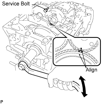
Align the drive and driven gear's timing marks (1 dot mark each) by turning the crankshaft with a wrench.
 |
Set the engine balancer.
 |
Install the engine balancer bolts.
- УКАЗАНИЕ:
- The engine balancer bolts are tightened in 2 progressive steps.
Step 1
Install and uniformly tighten the 8 bolts in several passes in the sequence shown.
- Момент затяжки:
- 50 Н*м{510 кгс*см, 37 фунт-сила-футов}
Step 2
Mark the front of the engine balancer bolts with paint.
Retighten the engine balancer bolts by 90° as shown.
Check that the painted mark is now at a 90° angle to the front.
|
Install the oil baffle plate with the 2 bolts (*1).
- Момент затяжки:
- 9.0 Н*м{92 кгс*см, 80 фунт-сила-дюймов}
Remove the service bolt from the engine balancer.
| 14. INSTALL ENGINE REAR OIL SEAL |
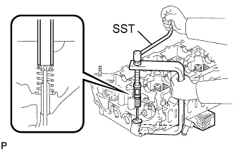
Using SST, tap in a new oil seal until its surface is flush with the oil seal retainer edge.
- Специальный инструмент (SST):
- 09223-56010
- ПРИМЕЧАНИЕ:
- Keep the lip free from foreign matter.
- Do not tap the oil seal at an angle.
 |
| 15. INSTALL VALVE SPRING SEAT |
Install the valve spring seat to the cylinder head.
| 16. INSTALL VALVE STEM OIL SEAL |
Apply a light coat of engine oil to a new oil seal.
Using SST, push in the oil seal.
- Специальный инструмент (SST):
- 09201-41020
- ПРИМЕЧАНИЕ:
- Failure to use SST will cause the seal to be damaged or improperly seated.
 |
| 17. INSTALL INTAKE VALVE |
Apply plenty of engine oil to the tip area of the intake valve shown in the illustration.
 |
Install the valve, compression spring and spring retainer to the cylinder head.
- ПРИМЕЧАНИЕ:
- Install the same parts in the same combination to the original locations.
Using SST and wooden blocks, compress the spring and install the 2 retainer locks.
- Специальный инструмент (SST):
- 09202-70020
 |
Using a 5 mm pin punch and plastic-faced hammer, lightly tap the valve stem tip to ensure a proper fit.
- ПРИМЕЧАНИЕ:
- Do not damage the valve stem tip.
 |
| 18. INSTALL EXHAUST VALVE |
Apply plenty of engine oil to the tip area of the intake valve shown in the illustration.
 |
Install the valve, compression spring and spring retainer to the cylinder head.
- ПРИМЕЧАНИЕ:
- Install the same parts in the same combination to the original locations.
Using SST and wooden blocks, compress the spring and install the 2 retainer locks.
- Специальный инструмент (SST):
- 09202-70020
 |
Using a 5 mm pin punch and plastic-faced hammer, lightly tap the valve stem tip to ensure a proper fit.
- ПРИМЕЧАНИЕ:
- Do not damage the valve stem tip.
 |
| 19. INSTALL VALVE LASH ADJUSTER ASSEMBLY |
Be sure to inspect the valve lash adjuster before installing it (see page RAV4_ACA30 RM000001VYE002X_01_0008.html).
Install the lash adjusters.
- ПРИМЕЧАНИЕ:
- Install the lash adjuster to the original position.
 |
| 20. INSTALL CYLINDER HEAD SUB-ASSEMBLY |
Check the piston protrusions for each cylinder.
Clean the cylinder block with solvent.
Set the piston of the cylinder to be measured to slightly before TDC.
Place a dial indicator on the cylinder block, and set the measuring tip as shown in the illustration.
Set the dial indicator at 0 mm (0 in.).
- УКАЗАНИЕ:
- Make sure that the measuring tip is square to the cylinder block gasket surface and piston head when taking the measurements.
Find where the piston head protrudes most by slowly turning the crankshaft clockwise and counterclockwise.
Measure each cylinder at 2 places as shown in the illustration, making a total of 8 measurements.
For the piston protrusion value of each cylinder, use the average of the 2 measurements of each cylinder.
If the protrusion is not as specified, remove the piston and connecting rod and reinstall it.- Standard piston protrusion:
- 0.300 to 0.560 mm (0.01181 to 0.02205 in.)

Select a new cylinder head gasket.
- УКАЗАНИЕ:
- Cylinder head gaskets are marked A, B, C, D or E accordingly.
- New installed cylinder head gasket thickness:
Cutout mark Specified Condition A 1.00 to 1.10 mm (0.0394 to 0.0433 in.) B 1.05 to 1.15 mm (0.0413 to 0.0453 in.) C 1.10 to 1.20 mm (0.0433 to 0.0472 in.) D 1.15 to 1.25 mm (0.0453 to 0.0492 in.) E 1.20 to 1.30 mm (0.0472 to 0.0512 in.)
Select the largest piston protrusion value from the measurements and then select a new appropriate gasket according to the table below.
- Piston protrusion:
Gasket size Specified Condition Use A 0.300 to 0.355 mm (0.01181 to 0.01398 in.) Use B 0.355 to 0.405 mm (0.01398 to 0.0159 in.) Use C 0.405 to 0.455 mm (0.0159 to 0.01791 in.) Use D 0.455 to 0.505 mm (0.01791 to 0.01988 in.) Use E 0.505 to 0.560 mm (0.01988 to 0.02205 in.)
 |
Using the crankshaft pulley bolt, set the No. 1 cylinder to 90° BTDC/compression.
 |
Place the cylinder head gasket in position on the cylinder block.
Place the cylinder head on the cylinder block.
- ПРИМЕЧАНИЕ:
- Be careful of the installation direction.
Apply a light coat of engine oil to the threads and under the heads of the cylinder head bolts.
Install the cylinder head bolts.
- УКАЗАНИЕ:
- For new bolts, perform steps 1 to 3. For used bolts, perform only step 1.
- If any bolt is broken or deformed, replace it.
Step 1
Install and uniformly tighten the 10 cylinder head bolts, in several steps in the sequence shown in the illustration.
- Момент затяжки:
- 50 Н*м{510 кгс*см, 37 фунт-сила-футов}
- УКАЗАНИЕ:
- If any one of the cylinder head bolts does not meet the torque specification, replace the cylinder head bolt.
Mark the front of the cylinder head bolt with paint.
Retighten the cylinder head bolts by 90° in the sequence shown in the illustration.
Perform the step above twice.
Check that the painted mark is positioned as shown in the illustration.

Step 2
Loosen the cylinder head bolts by 90° in the sequence shown in the illustration.
Perform the step above again.
Check that the painted mark is positioned as shown in the illustration.

Step 3
Retighten the cylinder head bolts by 90° in the sequence shown in the illustration.
Perform the step above twice.
Check that the painted mark is positioned as shown in the illustration.

| 21. INSTALL VALVE ROCKER ARM SUB-ASSEMBLY |
Set the 16 rocker arms to the lash adjusters.
- ПРИМЕЧАНИЕ:
- Before and after setting the camshaft and No. 2 camshaft, firmly set the rocker arm to the lash adjuster.
 |
| 22. INSTALL NO. 1 CAMSHAFT |
Install the No. 2 bearing cap.
 |
Apply clean engine oil to the cam of each camshaft, journals of the cylinder head and valve rocker arm.
 |
Place the No. 2 camshaft on the camshaft carrier as shown in the illustration so that the No. 1 and No. 3 cylinder cam lobes face upward.
- ПРИМЕЧАНИЕ:

- Before and after setting the camshaft and No. 2 camshaft, check that the rocker arm is firmly set to the lash adjuster.
 |
Align the camshaft and No. 2 camshaft timing mark (1 dot mark each).
 |
Place the camshaft on the camshaft carrier.
Set the camshaft bearing caps as shown in the illustration.
- УКАЗАНИЕ:
- Make sure of the marks and numbers on the camshaft bearing caps and place them in each proper position and direction.
 |
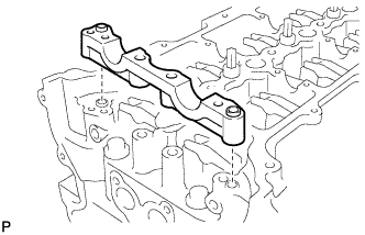
Set the oil delivery pipe, bolts and union bolts.
Temporarily tighten the 2 union bolts.
 |
Uniformly tighten the bolts in the sequence shown in the illustration.
- Момент затяжки:
- 10 Н*м{102 кгс*см, 7 фунт-сила-футов}for 1 to 16
- 25 Н*м{255 кгс*см, 18 фунт-сила-футов}for 17 to 20
Tighten the 2 union bolts.
- Момент затяжки:
- 17 Н*м{173 кгс*см, 13 фунт-сила-футов}
| 23. INSTALL CAMSHAFT TIMING SPROCKET |
Install the crankshaft timing sprocket, camshaft timing sprocket and chain.
 |
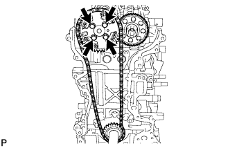
Install the camshaft timing sprocket by fitting the straight pin of the No. 2 camshaft into the hole on the camshaft timing sprocket.
Make sure that the timing mark of the timing sprocket and the paint mark of the timing chain align.
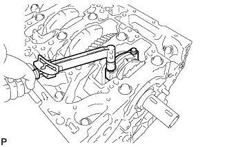
While holding the hexagon portion of the No. 2 camshaft, tighten the 4 bolts uniformly to install the camshaft timing sprocket to the No. 2 camshaft.
- Момент затяжки:
- 20 Н*м{204 кгс*см, 15 фунт-сила-футов}
 |
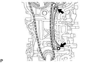
| 24. INSTALL NO. 1 CHAIN VIBRATION DAMPER |
Install the vibration damper with the 2 bolts.
- Момент затяжки:
- 21 Н*м{214 кгс*см, 15 фунт-сила-футов}
 |
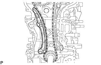
| 25. INSTALL CHAIN TENSIONER SLIPPER |
Install the tensioner slipper.
 |
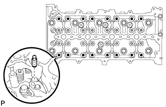
| 26. INSTALL NO. 1 CHAIN TENSIONER ASSEMBLY |
Move the stopper plate upward to release the lock, and push the plunger deep into the tensioner (*1).
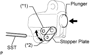 |
Move the stopper plate downward to set the lock, and insert SST into the stopper plate hole (*2).
- Специальный инструмент (SST):
- 09240-00020(09242-00200)
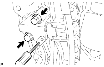
Install the chain tensioner with the 2 bolts.
- Момент затяжки:
- 9.0 Н*м{92 кгс*см, 80 фунт-сила-дюймов}
 |
Remove SST.
| 27. INSTALL TIMING CHAIN CASE OIL SEAL |
Place the timing chain cover on wooden blocks.
Using a screwdriver, pry out the oil seal.
- УКАЗАНИЕ:
- Tape the screwdriver tip before use.
- ПРИМЕЧАНИЕ:
- Do not damage the surface of the oil seal press fit hole.
 |
Using SST and a hammer, tap in a new oil seal to a depth between 0 to 0.6 mm (0 to 0.024 in.) from the timing chain cover edge.
- Специальный инструмент (SST):
- 09223-50010
- ПРИМЕЧАНИЕ:
- Keep the lip free from foreign matter.
- Do not tap the oil seal at an angle.
 |
Apply MP grease to the lip of the oil seal.
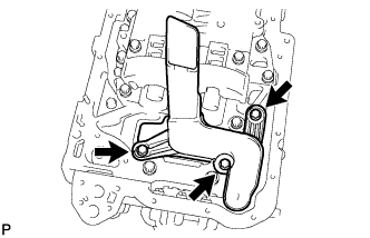
| 28. INSTALL TIMING CHAIN COVER SUB-ASSEMBLY (w/ Oil Pump) |
Install a new gasket and O-ring to the timing chain cover as shown in the illustration.
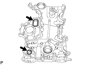 |
Apply seal packing in a continuous bead to the timing chain cover as shown in the illustration.

- Seal packing:
- Toyota genuine seal packing block, three bond 1207B or equivalent
- Standard seal width:
Position Specified Condition A - A 2.0 to 4.0 mm (0.079 to 0.157 in.) B - B 8.0 to 10.0 mm (0.315 to 0.394 in.) C - C Width: 13 mm (0.512 in.)
Height: 6 mm (0.236 in.)
- ПРИМЕЧАНИЕ:
- Be sure to clean and degrease the contact surfaces, especially 4 areas indicated by the arrows in the illustration.
- When the contact surfaces are wet, wipe them off with an oil-free cloth before applying seal packing.
- When applying seal packing to area C - C, apply it in the direction of the white arrows in the illustration.
- Install the crankcase within 3 minutes and tighten the bolts within 15 minutes after applying seal packing.
- Do not start the engine for at least 4 hours after installing.
Apply adhesive to the 4 bolts.
- Adhesive:
- Toyota genuine adhesive 1324, three bond 1324 or equivalent
- УКАЗАНИЕ:
- Bolt length: 37.5 mm (1.476 in.)
 |
Temporarily install the timing chain cover with the 4 bolts.
 |
Temporarily install a new seal washer and bolt A.
- УКАЗАНИЕ:
- Bolt length: 67.5 mm (2.657 in.)
Temporarily install the 8 bolts.
- УКАЗАНИЕ:
- Bolt length: 37.5 mm (1.476 in.)
Using several steps, install the 13 bolts.
- Момент затяжки:
- 31.5 Н*м{321 кгс*см, 23 фунт-сила-футов}for except A bolts
- 21 Н*м{214 кгс*см, 15 фунт-сила-футов}for A bolt
Using a 10 mm socket hexagon wrench, install the timing chain cover tight plug and a new gasket.
- Момент затяжки:
- 19 Н*м{194 кгс*см, 14 фунт-сила-футов}
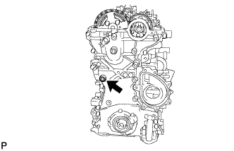 |
| 29. INSTALL WATER PUMP ASSEMBLY |
Install a new gasket onto the timing chain cover as shown in the illustration.
 |
Clean the 7 bolts and 7 bolt holes.
Temporarily install the water pump.
- Standard bolt length:
Item Specified Condition Bolt A and C 45 mm (1.77 in.) Bolt B 30 mm (1.18 in.)
Apply adhesive to 2 or 3 threads of the bolt labeled A.
- Adhesive:
- Toyota genuine adhesive 1324, three bond 1324 or equivalent.
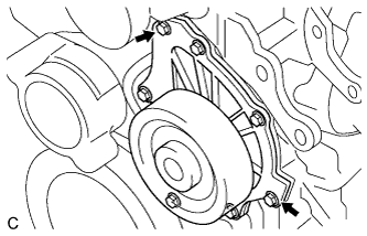
Temporarily install the water pump with the 7 bolts.
 |
Tighten the 2 bolts indicated by the arrows in the illustration. Then tighten the other bolts.
- Момент затяжки:
- 32 Н*м{326 кгс*см, 24 фунт-сила-футов}
 |
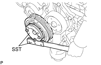
| 30. INSTALL CRANKSHAFT PULLEY |
Align the keyway of the pulley with the key located on the crankshaft, then slide the pulley into place.
Using SST, install the pulley bolt.
- Специальный инструмент (SST):
- 09213-58013
09330-00021
- Момент затяжки:
- 250 Н*м{2,550 кгс*см, 184 фунт-сила-футов}
 |
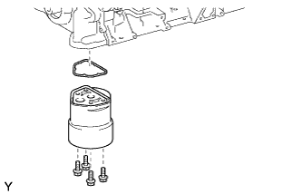
| 31. INSTALL OIL STRAINER SUB-ASSEMBLY |
Install a new O-ring and the oil strainer with the 3 bolts.
- Момент затяжки:
- 9.0 Н*м{92 кгс*см, 80 фунт-сила-дюймов}
 |
| 32. INSTALL OIL FILTER BRACKET |
Install a new gasket and the oil filter bracket with the 4 bolts.
- Момент затяжки:
- 9.0 Н*м{92 кгс*см, 80 фунт-сила-дюймов}
 |
| 33. INSTALL OIL FILTER ELEMENT |
Clean the oil filter cap threads and O-ring groove.
Apply a small amount of engine oil to a new O-ring and install it to the oil filter cap.
 |
Set a new oil filter element in the oil filter cap.
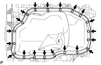
| 34. INSTALL NO. 2 OIL PAN SUB-ASSEMBLY |
Apply seal packing in a continuous bead as shown in the illustration.
- Seal packing:
- Toyota genuine seal packing black, three bond 1207B or equivalent
- Standard seal diameter:
- 4.0 to 7.0 mm (0.157 to 0.276 in.)
- ПРИМЕЧАНИЕ:
- Remove any oil from the contact surface.
- Install the oil pan within 3 minutes and tighten the bolts within 10 minutes after applying seal packing.
- Do not start the engine for at least 4 hours after installing.
 |
Install the oil pan with the 18 bolts and 2 nuts.
- Момент затяжки:
- 10.5 Н*м{107 кгс*см, 8 фунт-сила-футов}
 |
Install a new gasket and the drain plug.
- Момент затяжки:
- 38 Н*м{387 кгс*см, 28 фунт-сила-футов}
| 35. INSTALL NOZZLE HOLDER CLAMP SEAT |
Install the 4 nozzle holder clamp seats.
- Момент затяжки:
- 11 Н*м{112 кгс*см, 8 фунт-сила-футов}
| 36. INSTALL INJECTOR ASSEMBLY |
Install the nozzle seats to the cylinder head.
Install new O-rings to each injector.
 |
Apply a light coat of engine oil to the O-rings on each injector.
Install the injectors to the cylinder head.
- ПРИМЕЧАНИЕ:
- Fit the injectors to the nozzle seats.
Install the nozzle holder clamp as shown in the illustration.
 |
Install the nozzle holder clamp bolts by hand.
- ПРИМЕЧАНИЕ:
- Pay attention to the mounting orientation (beveled edge) of the washer.
- When temporarily attaching the nozzle holder clamp and the mounting bolt, be careful not to position them at an angle.
- УКАЗАНИЕ:
- Apply a light coat of engine oil on the threads of the nozzle holder clamp bolts.
Temporarily install the No. 1, No. 2, No. 3 and No. 4 injection pipes.
Temporarily install 5 new gaskets, the leakage pipe, bolt and 5 union bolts.
Tighten the 4 nozzle holder clamp bolts.
- Момент затяжки:
- 25 Н*м{255 кгс*см, 18 фунт-сила-футов}
Remove the 4 injection pipes.
| 37. INSTALL NO. 1 NOZZLE LEAKAGE PIPE ASSEMBLY |
Tighten the 5 union bolts.
- Момент затяжки:
- 18 Н*м{184 кгс*см, 13 фунт-сила-футов}for (*1)
- 22 Н*м{224 кгс*см, 16 фунт-сила-футов}for (*2)
 |
Check that there are no leaks from the nozzle leakage pipe connection.
Install SST (union), SST (inspection union bolt) and gasket.
- Специальный инструмент (SST):
- 09280-00010
09268-45014
(90405-06167)
- Момент затяжки:
- 21 Н*м{214 кгс*см, 15 фунт-сила-футов}
Apply a light coat of soapy water (any fluid to detect fuel leakage) on the No. 2 nozzle leakage pipe connection.
Attach SST (turbocharger pressure gauge) to the fuel return side of SST (union), and maintain 100 kPa (1.0 kgf/cm2, 14.5 psi) of pressure for 60 seconds to check that there are no bubbles coming from the pipe connection.
- Специальный инструмент (SST):
- 09992-00242
After checking for fuel leaks, wipe off the soapy water from the pipe connection.
Remove SST and gasket.


| 38. INSTALL OIL FILLER CAP SUB-ASSEMBLY |
Remove any dirt or foreign matter from the installation surface and inside of the engine.
Apply a small amount of engine oil to the O-ring again and install the oil filter cap.
- ПРИМЕЧАНИЕ:
- Be careful that the O-ring does not get caught between the parts.
Using SST, tighten the oil filter cap.
- Специальный инструмент (SST):
- 09228-06501
- Момент затяжки:
- 40 Н*м{408 кгс*см, 30 фунт-сила-футов}
- ПРИМЕЧАНИЕ:
- Make sure that the oil filter is installed securely as shown in the illustration.
- Be careful that the O-ring does not get caught between the parts.
 |
Apply a small amount of engine oil to a new drain plug O-ring, and install it to the oil filter cap.
- ПРИМЕЧАНИЕ:
- Before installing the O-ring, remove any dirt or foreign matter from the installation surface of the oil filter cap.
 |
Install the oil filter drain plug to the filter cap.
- Момент затяжки:
- 12.5 Н*м{127 кгс*см, 9 фунт-сила-футов}
- ПРИМЕЧАНИЕ:
- Be careful that the O-ring does not get caught between the parts.
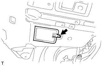
Close the oil filter element service cover and install the clip.
 |
| 39. INSTALL CYLINDER HEAD COVER SUB-ASSEMBLY |
Remove any old packing (FIPG) material.
Apply seal packing to the cylinder head as shown in the illustration.
- Seal packing:
- Toyota genuine seal packing block, three bond 1207B or equivalent.
- Standard seal diameter:
- 6 mm (0.23 in.)
 |
Install the gasket to the cylinder head cover.
Install the cylinder head cover with the 12 bolts, 2 nuts and 2 washers.
Uniformly tighten the bolts and nuts in several passes.- Момент затяжки:
- 11 Н*м{112 кгс*см, 8 фунт-сила-футов}
 |
| 40. INSTALL NOZZLE HOLDER SEAL |
Install the 4 nozzle holder seals.
- ПРИМЕЧАНИЕ:
- Apply a light coat of silicone oil on the nozzle holder seal side.