Engine Unit -- Disassembly |
| 1. REMOVE CAMSHAFT POSITION SENSOR |
Disconnect the sensor connector.
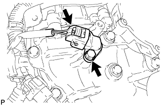 |
Remove the bolt and sensor.
| 2. REMOVE CRANKSHAFT POSITION SENSOR |
Disconnect the sensor connector.
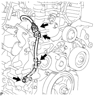 |
Disconnect the sensor connector from the bracket.
Disconnect the sensor wire harness clamp.
Remove the bolt and sensor.
| 3. REMOVE OIL FILLER CAP |
| 4. REMOVE CYLINDER HEAD COVER SUB-ASSEMBLY |
Disconnect the ventilation hose.
Remove the 2 nuts, 2 washers, 13 bolts, 4 nozzle holder clamp seats and cylinder head cover.
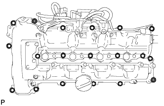 |
Remove the cylinder head cover gasket and cylinder head cover No. 2 gasket.
| 5. REMOVE NO. 2 OIL PAN SUB-ASSEMBLY |
Remove the 18 bolts and 2 nuts.
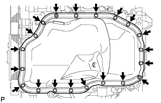 |
Insert the blade of SST between the oil pan and cylinder block, cut through the applied sealer and remove the oil pan.
- Специальный инструмент (SST):
- 09032-00100
- ПРИМЕЧАНИЕ:
- Do not use SST for the timing belt case side and rear oil seal retainer.
- Be careful not to damage the contact surfaces of the oil pan.
 |
Remove the gasket and drain plug.
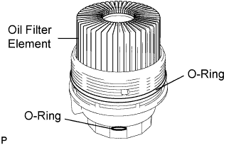
| 6. REMOVE OIL FILTER CAP ASSEMBLY |
Remove the clip and open the oil filter element service cover.
 |
Remove the oil filter drain plug and O-ring, and then insert the drain pipe into the oil filter cap and drain the engine oil into a container.
- УКАЗАНИЕ:
- The drain pipe is supplied with the oil filter element.
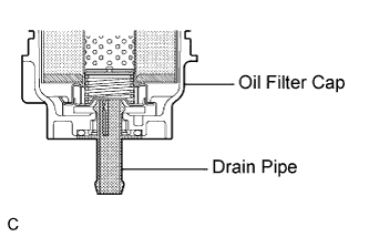 |
Using SST, remove the oil filter cap together with the oil filter element.
- Специальный инструмент (SST):
- 09228-06501
 |
| 7. REMOVE OIL FILTER ELEMENT |
Remove the oil filter element and 2 O-rings from the oil filter cap.
- ПРИМЕЧАНИЕ:
- Be sure to remove the O-ring (for the cap) by hand, without using any tools, to prevent damage to the groove for the O-ring on the cap.
 |
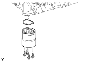
| 8. REMOVE OIL FILTER BRACKET |
Remove the 4 bolts, oil filter bracket and gasket.
 |
| 9. REMOVE OIL STRAINER SUB-ASSEMBLY |
Remove the 3 bolts, oil strainer and O-ring.
 |
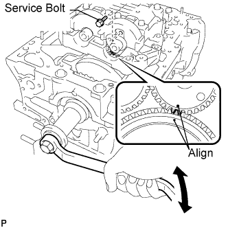
| 10. REMOVE CRANKSHAFT PULLEY |
Set the No. 1 piston to the TDC/compression.
Turn the crankshaft pulley clockwise to align the timing pointer of the timing chain cover and timing mark on the pulley.
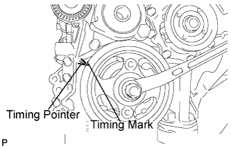
Make sure that the timing mark of the camshaft sprocket is at the top.
- УКАЗАНИЕ:
- If the timing mark is not at the top, turn the crankshaft pulley 1 revolution so that the timing mark comes to the top (Set the No. 1 piston to the TDC/compression).
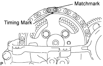 |
Put a matchmark on the timing chain plate that is aligned with the matchmark of the cam sprocket.
- УКАЗАНИЕ:
- The timing chain has 2 yellow-colored plates. If either of them is aligned with the matchmarks of the cam sprocket, this step can be omitted.
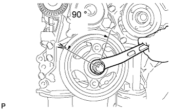
Turn the crankshaft by approximately 90° in the engine revolution direction at the point where the No. 1 piston is set to the TDC/compression so that the lifted valve and piston do not contact each other when removing the camshaft.
 |
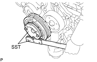
Using SST, remove the pulley bolt.
- Специальный инструмент (SST):
- 09213-58013
09330-00021
 |
Insert the service bolt.
- Recommended service bolt:
Item Specified Condition Thread diameter 22 mm (0.87 in.) Thread pitch 1.5 mm (0.059 in.) Bolt length Approx. 30 to 38 mm (1.18 to 1.50 in.)
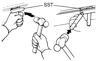
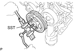
Using SST, remove the crankshaft pulley.
- Специальный инструмент (SST):
- 09950-50013(09951-05010,09952-05010,09953-05020,09954-05021)
 |
| 11. REMOVE WATER PUMP ASSEMBLY |
Remove the 7 bolts, water pump and gasket.
 |
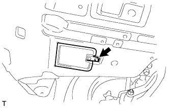
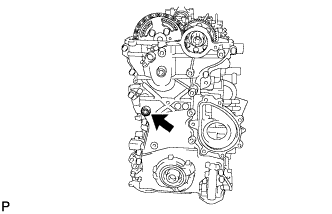
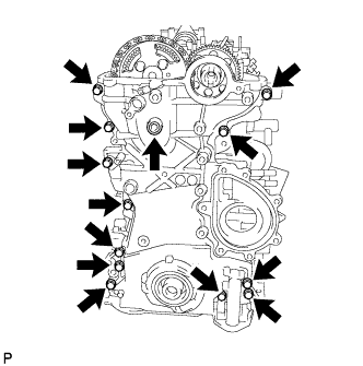
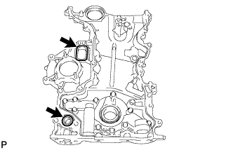
| 12. REMOVE TIMING CHAIN COVER SUB-ASSEMBLY (w/ Oil Pump) |
Using a 10 mm socket hexagon wrench, remove the timing chain cover tight plug and gasket.
 |
Remove the 13 bolts and seal washer as shown in the illustration.
 |
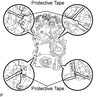
Remove the timing chain cover by prying between the timing chain cover and cylinder head or cylinder block with a screwdriver.
- УКАЗАНИЕ:
- Tape the screwdriver tip before use.
- ПРИМЕЧАНИЕ:
- Do not damage the contact surfaces of the cylinder head, cylinder block and timing chain cover.
 |
Remove the gasket and O-ring.
 |
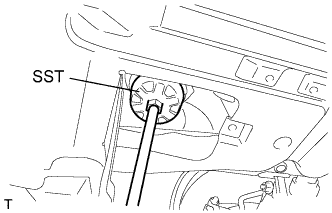
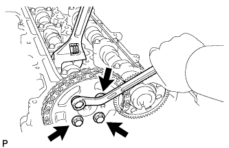
| 13. REMOVE NO. 1 CHAIN TENSIONER ASSEMBLY |
Move the stopper plate upward to release the lock, and push the plunger deep into the tensioner (*1).
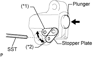 |
Move the stopper plate downward to set the lock, and insert SST into the stopper plate hole (*2).
- Специальный инструмент (SST):
- 09240-00020(09242-00200)
Remove the 2 bolts and chain tensioner.
 |
| 14. REMOVE CHAIN TENSIONER SLIPPER |
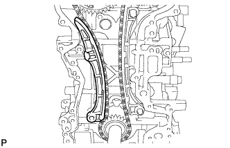 |
| 15. REMOVE NO. 1 CHAIN VIBRATION DAMPER |
Remove the 2 bolts and vibration damper.
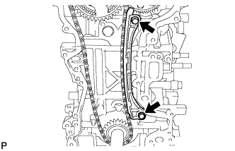 |
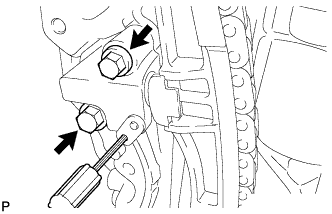
| 16. REMOVE CAMSHAFT TIMING SPROCKET |
Remove the 4 bolts on the sprocket while holding the hexagonal portion of the No. 2 camshaft.
 |
Remove the camshaft timing sprocket, crankshaft timing sprocket and chain.
| 17. REMOVE CAMSHAFT |
Using the crankshaft pulley bolt, set the No. 1 cylinder to 90° BTDC/compression.
 |
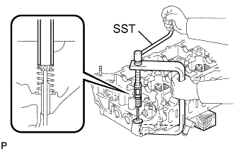
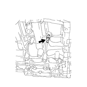
Remove the 2 union bolts.
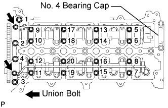 |
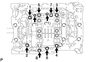
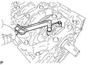
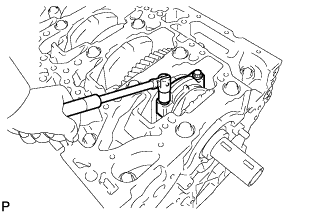
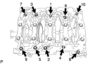
Using several steps, loosen and remove the 20 bearing cap bolts uniformly in the sequence shown in the illustration.
Remove the 8 bearing caps, No. 1 bearing cap and 2 oil delivery pipes.
- УКАЗАНИЕ:
- Do not remove the No. 4 bearing cap.
Remove the camshaft and No. 2 camshaft.
Remove the No. 2 bearing cap.
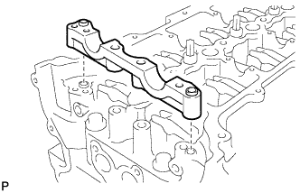 |
| 18. REMOVE NO. 1 VALVE ROCKER ARM SUB-ASSEMBLY |
Remove the 16 valve rocker arm.
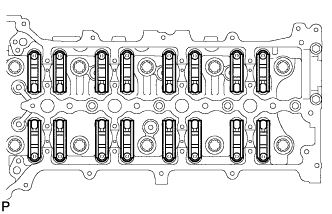 |
| 19. REMOVE VALVE LASH ADJUSTER ASSEMBLY |
Remove the valve lash adjusters from the cylinder head.
- УКАЗАНИЕ:
- Arrange the removed parts in the correct order.
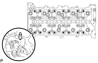 |
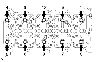
| 20. REMOVE CYLINDER HEAD SUB-ASSEMBLY |
Uniformly loosen the 10 bolts in the sequence shown in the illustration. Remove the 10 cylinder head bolts and plate washers.
- ПРИМЕЧАНИЕ:
- Do not drop washers into the cylinder head.
- Head warpage or cracking could result from removing bolts in the incorrect order.
 |
Remove the cylinder head and gasket.
| 21. REMOVE INTAKE VALVE |
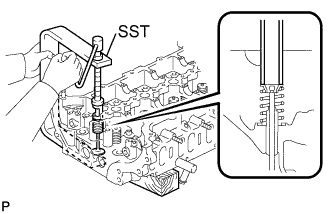
Using SST and wooden blocks, compress the compression spring and remove the valve retainer locks.
- Специальный инструмент (SST):
- 09202-70020
 |
Remove the retainer, compression spring and valve.
- УКАЗАНИЕ:
- Arrange the removed parts in the correct order.
| 22. REMOVE EXHAUST VALVE |
Using SST and wooden blocks, compress the compression spring and remove the valve retainer locks.
- Специальный инструмент (SST):
- 09202-70020
 |
Remove the retainer, compression spring and valve.
- УКАЗАНИЕ:
- Arrange the removed parts in the correct order.
| 23. REMOVE VALVE STEM OIL SEAL |
Using needle-nose pliers, remove the oil seal.
 |
| 24. REMOVE VALVE SPRING SEAT |
Using compressed air and a magnetic finger, remove the valve spring seat by blowing air onto it.
 |
| 25. INSPECT ENGINE BALANCER ASSEMBLY THRUST CLEARANCE |
Using a dial indicator, measure the thrust clearance while moving the balance shaft back and forth.
- Standard thrust clearance:
- 0.09 mm (0.0035 in.)
- Maximum thrust clearance:
- 0.11 mm (0.0043 in.)
 |
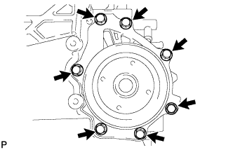
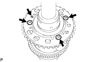
| 26. REMOVE ENGINE BALANCER ASSEMBLY |
Align the drive and driven gear's timing marks (1 dot mark each) by turning the crankshaft with a wrench.
 |
Install the service bolt.
- Recommended service bolt:
Item Specified Condition Thread diameter 6 mm (0.24 in.) Thread pitch 1 mm (0.04 in.) Bolt length 16 to 18 mm (0.63 to 0.71 in.)
- Момент затяжки:
- 1.5 Н*м{15 кгс*см, 13 фунт-сила-дюймов}
- УКАЗАНИЕ:
- When removing the balancer, make certain that the torsional spring force of the sub gear has been eliminated by installation of the service bolt.
Remove the 2 bolts and oil baffle plate (*1).
 |
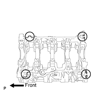
Uniformly loosen the 8 bolts in several steps, in the sequence shown in the illustration.
Remove the engine balancer.
| 27. INSPECT CONNECTING ROD THRUST CLEARANCE |
Using a dial indicator, measure the thrust clearance while moving the connecting rod back and forth.
- Standard thrust clearance:
- 0.10 to 0.45 mm (0.0039 to 0.0177 in.)
- Maximum thrust clearance:
- 0.55 mm (0.0217 in.)
 |
| 28. INSPECT CONNECTING ROD OIL CLEARANCE |
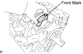
Check that the front marks on the connecting rod and cap are aligned to ensure the correct reassembly.
- ПРИМЕЧАНИЕ:
- The front marks on the connecting rods and caps are for ensuring the correct reassembly.
 |
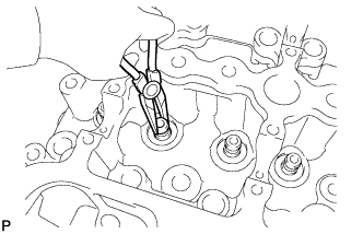
Remove the 2 connecting rod cap bolts.
Using the 2 removed connecting rod cap bolts, remove the connecting rod cap and lower bearing by wiggling the connecting rod cap right and left.
- УКАЗАНИЕ:
- Keep the lower bearing inserted to the connecting rod cap.
 |
Clean the crank pin and bearing.
Check the crank pin and bearing for pitting and scratches.
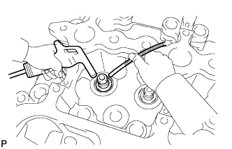
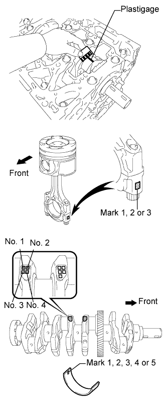
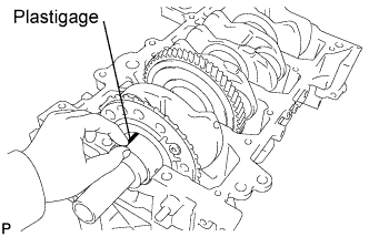
Lay a strip of Plastigage on the crank pin.
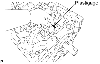 |
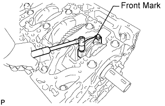
Check that the front mark of the connecting rod cap is facing forward.
 |
Install and alternately tighten the bolts of the connecting rod cap in several steps.
- ПРИМЕЧАНИЕ:
- Do not turn the crankshaft.
- Момент затяжки:
- 40 Н*м{408 кгс*см, 30 фунт-сила-футов}
 |
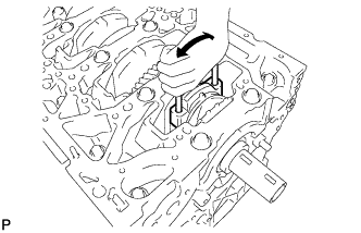
Mark the front side of each connecting cap bolt with paint.
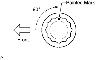 |
Retighten the cap bolts by 90° as shown.
Check that the painted mark is now at a 90° angle to the front.
- ПРИМЕЧАНИЕ:
- Do not turn the crankshaft.
Remove the 2 connecting rod cap bolts.
 |
Using the 2 removed connecting rod cap bolts, remove the connecting rod cap and lower bearing by wiggling the connecting rod cap right and left.
- УКАЗАНИЕ:
- Keep the lower bearing inserted to the connecting rod cap.
Measure the Plastigage at its widest point.
- Standard oil clearance:
- 0.024 to 0.042 mm (0.0009 to 0.0017 in.)
- Maximum oil clearance:
- 0.070 mm (0.0027 in.)
- УКАЗАНИЕ:
- If using a standard bearing, replace it with one that has the same number. If the number of the bearing cannot be determined, select the correct bearing by adding together the numbers imprinted on the crankshaft and connecting rod, then selecting the bearing with the same number as the total. There are 5 sizes of standard bearings, marked 1, 2, 3, 4 and 5.
Connecting rod cap "3" + Crankshaft "1" = Total number 4 (Use bearing "4")- Reference:
- Connecting rod big end inside diameter:
Mark Thickness 1 53.000 to 53.006 mm (2.0866 to 2.0869 in.) 2 53.006 to 53.012 mm (2.0869 to 2.0871 in.) 3 53.012 to 53.018 mm (2.0871 to 2.0873 in.) - Crankshaft pin diameter:
Mark Thickness 0 49.994 to 50.000 mm (1.9683 to 1.9685 in.) 1 49.988 to 49.994 mm (1.9680 to 1.9683 in.) 2 49.982 to 49.988 mm (1.9678 to 1.9680 in.) - Standard sized bearing center wall thickness:
Mark Thickness 1 1.485 to 1.488 mm (0.0585 to 0.0586 in.) 2 1.488 to 1.491 mm (0.0586 to 0.0587 in.) 3 1.491 to 1.494 mm (0.0587 to 0.0588 in.) 4 1.494 to 1.497 mm (0.0588 to 0.0589 in.) 5 1.497 to 1.500 mm (0.0589 to 0.0591 in.)
 |
Completely remove the Plastigage.
| 29. REMOVE PISTON SUB-ASSEMBLY WITH CONNECTING ROD |
Using a ridge reamer, remove all the carbon from the top of the cylinder.
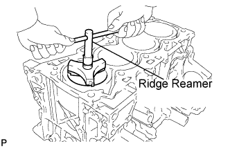 |
Push the piston, connecting rod assembly and upper bearing through the top of the cylinder block.
- УКАЗАНИЕ:
- Keep the bearing, connecting rod and cap together.
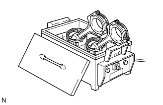
- Arrange the piston and connecting rod assemblies in the correct order.
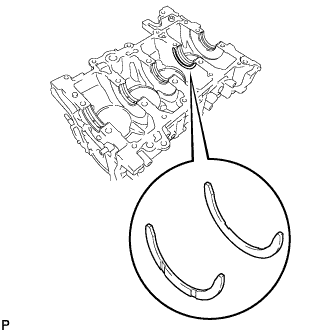
| 30. REMOVE CONNECTING ROD BEARING |
- УКАЗАНИЕ:
- Arrange the removed parts in the correct order.
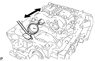
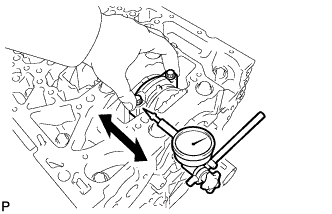
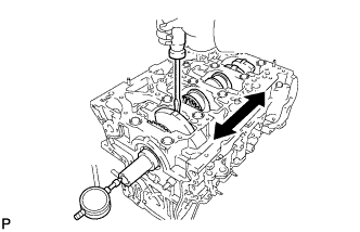
| 31. INSPECT CRANKSHAFT THRUST CLEARANCE |
Using a dial indicator, measure the thrust clearance while prying the crankshaft back and forth with a screwdriver.
- Standard thrust clearance:
- 0.04 to 0.24 mm (0.0016 to 0.0094 in.)
- Maximum thrust clearance:
- 0.30 mm (0.0118 in.)
- Standard thrust washer thickness:
- 1.93 to 1.98 mm (0.0760 to 0.0780 in.)
 |
| 32. REMOVE CRANKSHAFT AND CRANKSHAFT OIL CLEARANCE |
Uniformly loosen the 10 bolts in several steps, in the sequence shown in the illustration.
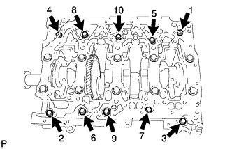 |
Uniformly loosen the 10 bearing cap bolts in several steps, in the sequence shown in the illustration.
 |
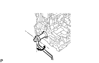
Remove the crankshaft bearing cap by prying between the crankshaft bearing cap and cylinder block with a screwdriver.
- ПРИМЕЧАНИЕ:
- Do not damage the contact surfaces of the cylinder block and crankshaft bearing cap.
- УКАЗАНИЕ:
- Keep the lower bearings and crankshaft bearing caps together.
- Arrange the thrust washers in the correct order.
- Keep the upper crankshaft bearings and upper thrust washers together with the cylinder block.
- Tape the screwdriver tip before use.
 |
Clean each main journal and bearing.
Check each main journal and bearing for pitting and scratches.
- УКАЗАНИЕ:
- If the journal or bearing is damaged, replace the bearing.
Place the crankshaft on the cylinder block.
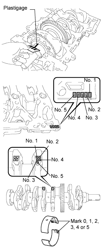
Lay a strip of Plastigage across each journal.
 |
Place the crankshaft bearing cap assembly on the cylinder block.
Install the crankshaft bearing cap bolts.
- УКАЗАНИЕ:
- The main bearing cap bolts are tightened in 2 progressive steps.
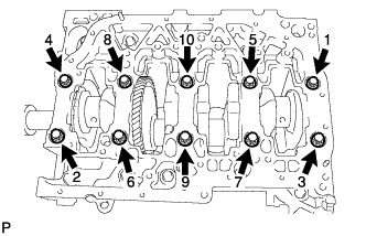
Step 1
Install and uniformly tighten the 10 main bearing cap bolts in the sequence shown in the illustration.
- Момент затяжки:
- 60 Н*м{612 кгс*см, 44 фунт-сила-футов}
- УКАЗАНИЕ:
- If any of the main bearing cap bolts does not meet the torque specification, replace the main bearing cap bolt.
- ПРИМЕЧАНИЕ:
- Do not turn the crankshaft.

Step 2
Mark the front of the bearing cap bolts with paint.
Retighten the bearing cap bolts by 90° as shown.
Check that the painted mark is now at a 90° angle to the front.
Install and uniformly tighten the 10 bolts, in several passes in the sequence shown.
- Момент затяжки:
- 18 Н*м{184 кгс*см, 13 фунт-сила-футов}
 |
Remove the crankshaft bearing cap.
Measure the Plastigage at its widest point.
- Standard oil clearance:
Bearing Cap Specified Condition No. 3 0.020 to 0.038 mm (0.00079 to 0.00149 in.) Others 0.014 to 0.032 mm (0.00055 to 0.00126 in.)
- Maximum oil clearance:
- 0.10 mm (0.0039 in.)
- УКАЗАНИЕ:
- If using a standard bearing, replace it with one having the same number. If the number of the bearing cannot be determined, select the correct bearing by adding together the numbers imprinted on the cylinder block and crankshaft, then selecting the bearing with the same number as the total.
- There are 5 sizes of standard bearings, marked 0, 1, 2, 3 and 4.
Cylinder block "2" + Crankshaft "1" = Total number 3 (Use bearing "3")- Reference:
- Standard cylinder block main journal bore diameter:
Mark Specified Condition 0 (No. 3 Journal) 63.000 to 63.006 mm (2.48031 to 2.48055 in.) 1 (No. 3 Journal) 63.006 to 63.012 mm (2.48055 to 2.48078 in.) 2 (No. 3 Journal) 63.012 to 63.018 mm (2.48078 to 2.48102 in.) 1 (Others) 63.000 to 63.006 mm (2.48031 to 2.48055 in.) 2 (Others) 63.006 to 63.012 mm (2.48055 to 2.48078 in.) 3 (Others) 63.012 to 63.018 mm (2.48078 to 2.48102 in.) - Standard crankshaft journal diameter:
Mark Specified Condition 0 58.994 to 59.000 mm (2.32259 to 2.32283 in.) 1 58.988 to 58.994 mm (2.32236 to 2.32259 in.) 2 58.982 to 58.988 mm (2.32212 to 2.32236 in.) - Standard sized bearing center wall thickness:
Mark Specified Condition 0 1.987 to 1.990 mm (0.07823 to 0.07835 in.) 1 1.990 to 1.993 mm (0.07835 to 0.07846 in.) 2 1.993 to 1.996 mm (0.07846 to 0.07858 in.) 3 1.996 to 1.999 mm (0.07858 to 0.07870 in.) 4 1.999 to 2.002 mm (0.07870 to 0.07881 in.) 5 2.002 to 2.005 mm (0.07881 to 0.07894 in.)
 |
Completely remove the Plastigage.
Lift out the crankshaft.
Remove the upper bearings and upper thrust washers from the cylinder block.
- УКАЗАНИЕ:
- Arrange the bearings and thrust washers in the correct order.
 |
| 33. REMOVE NO. 2 CRANKSHAFT BEARING |
Remove the lower bearings from the crankshaft bearing cap.
- УКАЗАНИЕ:
- Arrange the bearings in the correct order.
| 34. REMOVE ENGINE REAR OIL SEAL |
Remove the rear oil seal from the crankshaft.
| 35. REMOVE NO. 1 CRANKSHAFT POSITION SENSOR PLATE |
Using a T30 "torx" socket wrench, remove the 3 bolts and crankshaft position sensor plate.
 |
| 36. REMOVE PISTON RING SET |
- УКАЗАНИЕ:
- Arrange the piston rings in the correct order.
Using a piston ring expander, remove the 2 compression rings.
 |
Using a piston ring expander, remove the oil ring rail.
Remove the oil ring expander by hand.
| 37. REMOVE CYLINDER BLOCK WATER DRAIN COCK SUB-ASSEMBLY |
Remove the water drain cock from the cylinder block.
 |
Remove the water drain cock plug from the water drain cock.
| 38. REMOVE PISTON WITH PIN SUB-ASSEMBLY |
Check the fitting condition between the piston and piston pin.
Try to move the piston back and forth on the piston pin.
- УКАЗАНИЕ:
- If any movement is felt, replace the piston and pin as a set.
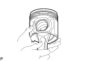 |
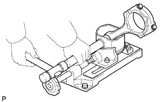
Disconnect the connecting rod from the piston.
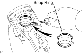
Using a screwdriver, pry off the snap rings from the piston.
Gradually heat the piston to approximately 80 to 90°C (176 to 194°F).
Using a brass bar and plastic-faced hammer, lightly tap out the piston pin and remove the connecting rod.
- УКАЗАНИЕ:
- The piston and pin are a matched set.
- Arrange the pistons, pins, rings, connecting rods and bearings in the correct order.
 |
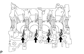
| 39. REMOVE NO. 1 OIL NOZZLE SUB-ASSEMBLY |
Using a 5 mm hexagon wrench, remove the oil nozzles.
 |
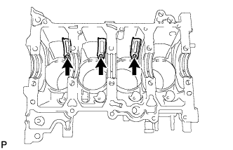
| 40. REMOVE OIL REFLECTOR PLATE |
Using a 5 mm hexagon wrench, remove the reflector plate.
 |