Fuel Injector -- Installation |
| 1. INSTALL INJECTOR ASSEMBLY |
Install the nozzle seats to the cylinder head.
Install new O-rings to each injector.
 |
Apply a light coat of engine oil to the O-rings on each injector.
Install the injectors to the cylinder head.
- ПРИМЕЧАНИЕ:
- Fit the injectors to the nozzle seats.
Install the nozzle holder clamp as shown in the illustration.
 |
Install the nozzle holder clamp bolts by hand.
- ПРИМЕЧАНИЕ:
- Pay attention to the mounting orientation (beveled edge) of the washer.
- When temporarily attaching the nozzle holder clamp and the mounting bolt, be careful not to position them at an angle.
- УКАЗАНИЕ:
- Apply a light coat of engine oil on the threads of the nozzle holder clamp bolts.
Temporarily install the No. 1, No. 2, No. 3 and No. 4 injection pipes.
Temporarily install 5 new gaskets, the leakage pipe, bolt and 5 union bolts.
Tighten the 4 nozzle holder clamp bolts.
- Момент затяжки:
- 25 Н*м{255 кгс*см, 18 фунт-сила-футов}
Remove the 4 injection pipes.
| 2. INSTALL NO. 1 NOZZLE LEAKAGE PIPE ASSEMBLY |
Tighten the 5 union bolts.
- Момент затяжки:
- 18 Н*м{184 кгс*см, 13 фунт-сила-футов}for (*1)
- 22 Н*м{224 кгс*см, 16 фунт-сила-футов}for (*2)
 |
Check that there are no leaks from the nozzle leakage pipe connection.
Install SST (union), SST (inspection union bolt) and gasket.
- Специальный инструмент (SST):
- 09280-00010
09268-45014
(90405-06167)
- Момент затяжки:
- 21 Н*м{214 кгс*см, 15 фунт-сила-футов}
Apply a light coat of soapy water (any fluid to detect fuel leakage) on the No. 2 nozzle leakage pipe connection.
Attach SST (turbocharger pressure gauge) to the fuel return side of SST (union), and maintain 100 kPa (1.0 kgf/cm2, 14.5 psi) of pressure for 60 seconds to check that there are no bubbles coming from the pipe connection.
- Специальный инструмент (SST):
- 09992-00242
After checking for fuel leaks, wipe off the soapy water from the pipe connection.
Remove SST and gasket.


| 3. INSTALL CYLINDER HEAD COVER SUB-ASSEMBLY |
Remove any old packing (FIPG) material.
Apply seal packing to the cylinder head as shown in the illustration.
- Seal packing:
- Toyota Genuine Seal Packing Black, Tree Bond 1207B or equivalent.
Standard seal diameter: 6 mm (0.24 in.)
 |
Install the gasket to the cylinder head cover.
Install the cylinder head cover with the 12 bolts, 2 washers and 2 nuts.
Uniformly tighten the bolts and nuts in several passes.- Момент затяжки:
- 11 Н*м{112 кгс*см, 8 фунт-сила-футов}
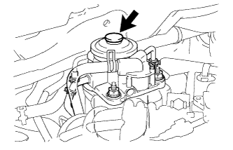
 |
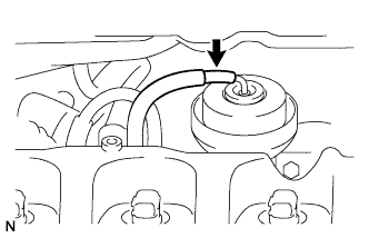
Connect the vacuum hose to the turbocharger actuator.
 |
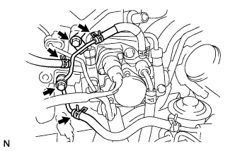
Align the connector with the pipe, then push in the connector to the pipe until it makes a "click" sound to connect the vacuum hose (*1).
 |
Connect the vacuum hose to the vacuum pump (*2).
Connect the power steering hose to the vacuum pump.
 |
Install the bolt.
| 4. INSTALL NOZZLE HOLDER SEAL |
Install the 4 nozzle holder seals.
- ПРИМЕЧАНИЕ:
- Apply a light coat of silicone oil on the nozzle holder seal side.
| 5. INSTALL NO. 2 NOZZLE LEAKAGE PIPE |
Install the No. 2 nozzle leakage pipe, a new gasket and the 2 bolts.
 |
Using pliers, grip the claws of the 3 clips and slide the 3 clips to connect the 3 fuel hoses.
| 6. INSTALL INJECTION PIPE SUB-ASSEMBLY |
- ПРИМЕЧАНИЕ:
- If an injector is replaced, the injection pipes must also be replaced.
Temporarily install the 4 injection pipes.
 |
Using SST, tighten the 4 nuts at the common rail end of the 4 injection pipes.
- Специальный инструмент (SST):
- 09023-38401
- Момент затяжки:
- 27 Н*м{275 кгс*см, 20 фунт-сила-футов}for use with SST
- 30 Н*м{306 кгс*см, 25 фунт-сила-футов}for use without SST
- УКАЗАНИЕ:
- Use of the proper SST is required to ensure that the correct torque is applied to the injection pipe nut.
- Use a torque wrench with a fulcrum length of 30 cm (11.81 in.).
- Make sure that the pipe is not deformed or twisted during installation.
If the pipe is deformed or twisted, or if it cannot be installed properly, replace the pipe with a new pipe.
Using SST, tighten the 4 nuts at the injector end of the 4 injection pipes.
- Специальный инструмент (SST):
- 09023-12701
- Момент затяжки:
- 31 Н*м{316 кгс*см, 23 фунт-сила-футов}for use with SST
- 34 Н*м{347 кгс*см, 25 фунт-сила-футов}for use without SST
- УКАЗАНИЕ:
- Use of the proper SST is required to ensure that the correct torque is applied to the injection pipe nut.
- Use a torque wrench with a fulcrum length of 30 cm (11.81 in.).
- Make sure that the pipe is not deformed or twisted during installation.
If the pipe is deformed or twisted, or if it cannot be installed properly, replace the pipe with a new pipe.
Install the 4 injection pipe clamps and 2 bolts.
- Момент затяжки:
- 5.0 Н*м{51 кгс*см, 44 фунт-сила-дюймов}
| 7. INSTALL FUEL INLET PIPE SUB-ASSEMBLY |
Temporarily install the fuel inlet pipe with the 2 clamps and nut.
 |
Using SST, tighten the nut at the common rail end of the fuel inlet pipe.
- Специальный инструмент (SST):
- 09023-38401
- Момент затяжки:
- 27 Н*м{275 кгс*см, 20 фунт-сила-футов}for use with SST
- 30 Н*м{306 кгс*см, 25 фунт-сила-футов}for use without SST
- УКАЗАНИЕ:
- Use of the proper SST is required to ensure that the correct torque is applied to the injection pipe nut.
- Use a torque wrench with a fulcrum length of 30 cm (11.81 in.).
- Make sure that the pipe is not deformed or twisted during installation.
If the pipe is deformed or twisted, or if it cannot be installed properly, replace the pipe with a new pipe.
Using SST, tighten the nut at the supply pump end of the fuel inlet pipe.
- Специальный инструмент (SST):
- 09023-38401
- Момент затяжки:
- 27 Н*м{275 кгс*см, 20 фунт-сила-футов}for use with SST
- 30 Н*м{306 кгс*см, 25 фунт-сила-футов}for use without SST
- УКАЗАНИЕ:
- Use of the proper SST is required to ensure that the correct torque is applied to the injection pipe nut.
- Use a torque wrench with a fulcrum length of 30 cm (11.81 in.).
- Make sure that the pipe is not deformed or twisted during installation.
If the pipe is deformed or twisted, or if it cannot be installed properly, replace the pipe with a new pipe.
Tighten the fuel inlet pipe clamp nut.
- Момент затяжки:
- 5.0 Н*м{51 кгс*см, 44 фунт-сила-дюймов}
| 8. INSTALL AIR CLEANER ASSEMBLY WITH ELEMENT |
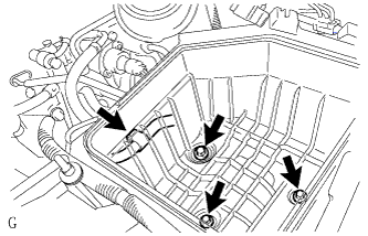
Install the cleaner case with the 3 bolts and connect the wire harness clamp.
- Момент затяжки:
- 5.0 Н*м{51 кгс*см, 44 фунт-сила-дюймов}
 |
Install the air filter element.
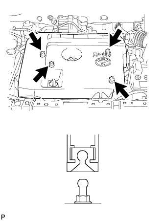
| 9. INSTALL AIR CLEANER CAP SUB-ASSEMBLY |
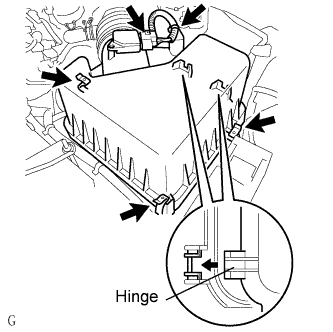
Insert the hinge parts of the air cleaner cap into the air cleaner case, and then hang the 3 hook clamps.
 |
Connect the mass air flow meter connector.
Engage the wire harness clamp.
| 10. CONNECT ENGINE WIRE |
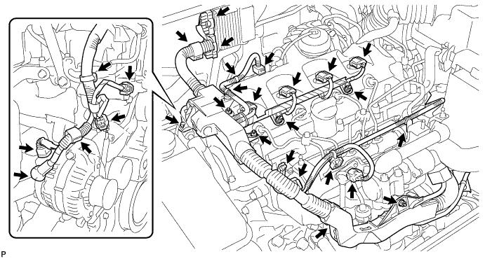
Connect the engine wire to the wire bracket with the nut.
- Момент затяжки:
- 7.5 Н*м{76 кгс*см, 66 фунт-сила-дюймов}
Connect the engine wire to the engine cover bracket with the bolt and 2 nuts.
- Момент затяжки:
- 7.5 Н*м{76 кгс*см, 66 фунт-сила-дюймов}
Connect the pressure sensor connector and 2 clamps.
Connect the common rail connector.
Connect the glow plug wire harness with the nut and grommet.
- Момент затяжки:
- 2.2 Н*м{22 кгс*см, 19 фунт-сила-дюймов}
Connect the 4 injector connectors and install the 2 nuts.
- Момент затяжки:
- 7.5 Н*м{76 кгс*см, 66 фунт-сила-дюймов}
Connect the vacuum regulating valve connector and 2clamps.
Connect the 2 injector driver connectors and clamp.
Install the nut and connect the 3 sensor connectors, 2 clamps and generator wire.
- Момент затяжки:
- 9.8 Н*м{100 кгс*см, 7 фунт-сила-футов}
| 11. CONNECT CABLE TO NEGATIVE BATTERY TERMINAL |
| 12. PERFORM REGISTRATION OF INJECTOR COMPENSATION CODE |
- УКАЗАНИЕ:
- Each injector assembly has a characteristic fuel injecting behavior (see page RAV4_ACA30 RM000000TJ400AX.html).
| 13. BLEED AIR FROM FUEL SYSTEM |
Using the hand pump, bleed air from the fuel system until pumping becomes difficult.
 |
| 14. CHECK FOR FUEL LEAKS |
PERFORM ACTIVE TEST
Connect the intelligent tester to the DLC3.
Start the engine.
Turn the intelligent tester ON.
Enter the following menus: Powertrain / Engine / Active Test.
Perform the Active Test.
Intelligent Tester Display Test Details Control Range Diagnostic Notes Test the Fuel Leak Pressurizing common rail internal fuel pressure, and checking for fuel leaks Stop/Start - Fuel pressure inside common rail pressurized to specified value and engine speed increased to 2,000 rpm when start is selected
- Above conditions to be maintained while test is started
- Fuel pressure inside common rail pressurized to specified value and engine speed increased to 2,000 rpm when start is selected
| 15. INSTALL NO. 1 ENGINE COVER |
Attach the 4 clips to install the engine cover.
 |