INSPECT NO. 1 OUTPUT SHAFT
INSPECT 1ST DRIVEN GEAR THRUST CLEARANCE
INSPECT 1ST DRIVEN GEAR RADIAL CLEARANCE
INSPECT 2ND DRIVEN GEAR THRUST CLEARANCE
INSPECT 2ND DRIVEN GEAR RADIAL CLEARANCE
INSPECT 3RD DRIVEN GEAR THRUST CLEARANCE
INSPECT 3RD DRIVEN GEAR RADIAL CLEARANCE
INSPECT 4TH DRIVEN GEAR THRUST CLEARANCE
INSPECT 4TH DRIVEN GEAR RADIAL CLEARANCE
INSPECT 5TH DRIVEN GEAR THRUST CLEARANCE
INSPECT 5TH DRIVEN GEAR RADIAL CLEARANCE
INSPECT 6TH DRIVEN GEAR THRUST CLEARANCE
INSPECT 6TH DRIVEN RADIAL CLEARANCE
INSPECT REVERSE DRIVEN GEAR THRUST CLEARANCE
INSPECT REVERSE DRIVEN GEAR RADIAL CLEARANCE
INSPECT 1ST AND 2ND SHIFT FORK SHAFT
INSPECT 3RD AND 4TH SHIFT FORK SHAFT
INSPECT 5TH AND 6TH SHIFT FORK SHAFT
INSPECT REVERSE SHIFT FORK SHAFT
INSPECT NO. 5 GEAR SHIFT FORK SHAFT
INSPECT NO. 1 GEAR SHIFT FORK
INSPECT NO. 2 GEAR SHIFT FORK
INSPECT NO. 3 GEAR SHIFT FORK
INSPECT REVERSE SHIFT FORK
INSPECT NO. 2 GEAR SHIFT HEAD
INSPECT NO. 3 GEAR SHIFT HEAD
INSPECT 1ST DRIVEN GEAR
INSPECT 2ND DRIVEN GEAR
INSPECT 3RD DRIVEN GEAR
INSPECT 4TH DRIVEN GEAR
INSPECT 1ST DRIVEN GEAR SYNCHRONIZER RING SET
INSPECT 2ND DRIVEN GEAR SYNCHRONIZER RING SET
INSPECT 3RD DRIVEN GEAR SYNCHRONIZER RING SET
INSPECT 4TH DRIVEN GEAR SYNCHRONIZER RING SET
INSPECT NO. 1 TRANSMISSION HUB SLEEVE
INSPECT NO. 2 TRANSMISSION HUB SLEEVE
INSPECT NO. 2 OUTPUT SHAFT
INSPECT 5TH DRIVEN GEAR
INSPECT 6TH DRIVEN GEAR
INSPECT REVERSE DRIVEN GEAR
INSPECT 5TH DRIVEN SYNCHRONIZER RING SET
INSPECT 6TH DRIVEN SYNCHRONIZER RING SET
INSPECT REVERSE DRIVEN SYNCHRONIZER RING SET
INSPECT NO. 3 TRANSMISSION HUB SLEEVE
INSPECT NO. 4 TRANSMISSION HUB SLEEVE
Output Shaft -- Inspection |
| 1. INSPECT NO. 1 OUTPUT SHAFT |
Check the No. 1 output shaft for wear and damage.
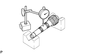
Using a dial indicator, check the No. 1 output shaft runout.
- Maximum runout:
- 0.03 mm (0.0012 in.)
If the runout exceeds the maximum, replace the No. 1 output shaft.
Using a micrometer, measure the diameter of the No. 1 output shaft journal surface.
- Standard diameter:
Measured Part
| Specified Condition
|
A
| 32.002 to 32.018 mm (1.2599 to 1.2605 in.)
|
B
| 35.084 to 36.000 mm (1.3813 to 1.4173 in.)
|
C
| 42.000 to 41.984 mm (1.6535 to 1.6529 in.)
|
D
| 42.000 to 41.989 mm (1.6535 to 1.6531 in.)
|
E
| 47.000 to 46.984 mm (1.8504 to 1.8498 in.)
|
F
| 36.002 to 36.018 mm (1.4174 to 1.4180 in.)
|
If the outer diameter is not as specified, replace the No. 1 output shaft.
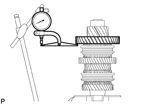
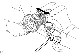
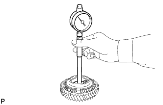
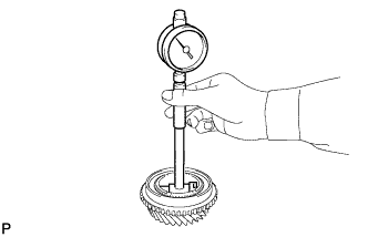
| 2. INSPECT 1ST DRIVEN GEAR THRUST CLEARANCE |
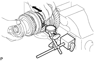
Using a dial indicator, measure the thrust clearance.
- Standard thrust clearance:
- 0.10 to 0.35 mm (0.0039 to 0.0138 in.)
- Maximum thrust clearance:
- 0.35 mm (0.0138 in.)
If the thrust clearance exceeds the maximum, replace the 1st driven gear, needle roller bearing or shaft.
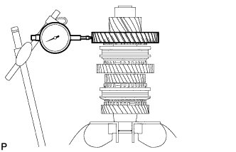
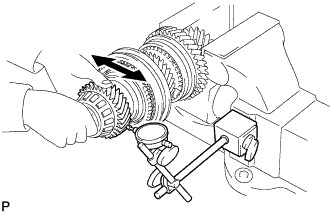
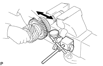
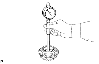
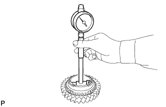
| 3. INSPECT 1ST DRIVEN GEAR RADIAL CLEARANCE |
Using a dial indicator, measure the radial clearance.
- Standard radial clearance:
- 0.015 to 0.068 mm (0.0006 to 0.0027 in.)
- Maximum radial clearance:
- 0.068 mm (0.0027 in.)
If the radial clearance exceeds the maximum, replace the 1st driven gear, needle roller bearing or shaft.
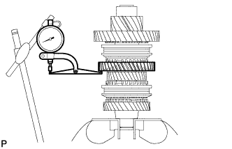
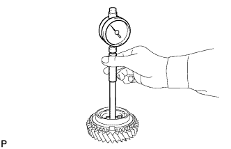
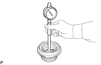
| 4. INSPECT 2ND DRIVEN GEAR THRUST CLEARANCE |
Using a dial indicator, measure the thrust clearance.
- Standard thrust clearance:
- 0.11 to 0.46 mm (0.0043 to 0.0181in.)
- Maximum thrust clearance:
- 0.46 mm (0.0181 in.)
If the thrust clearance exceeds the maximum, replace the 2nd driven gear, needle roller bearing or shaft.
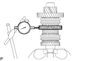
| 5. INSPECT 2ND DRIVEN GEAR RADIAL CLEARANCE |
Using a dial indicator, measure the radial clearance.
- Standard radial clearance:
- 0.015 to 0.048 mm (0.0006 to 0.0019 in.)
- Maximum radial clearance:
- 0.048 mm (0.0019 in.)
If the radial clearance exceeds the maximum, replace the 2nd driven gear, needle roller bearing or shaft.
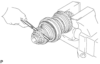
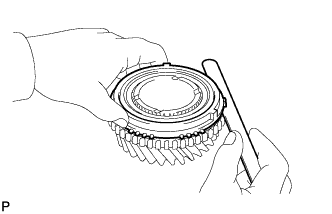
| 6. INSPECT 3RD DRIVEN GEAR THRUST CLEARANCE |
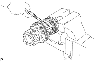
Using a feeler gauge, measure the thrust clearance.
- Standard thrust clearance:
- 0.11 to 0.54 mm (0.0043 to 0.0213 in.)
- Maximum thrust clearance:
- 0.54 mm (0.0213 in.)
If the thrust clearance exceeds the maximum, replace the 3rd driven gear, needle roller bearing or shaft.
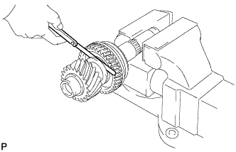
| 7. INSPECT 3RD DRIVEN GEAR RADIAL CLEARANCE |
Using a dial indicator, measure the radial clearance.
- Standard radial clearance:
- 0.015 to 0.066 mm (0.0006 to 0.0026 in.)
- Maximum radial clearance:
- 0.066 mm (0.0026 in.)
If the radial clearance exceeds the maximum, replace the 3rd driven gear, needle roller bearing or shaft.
| 8. INSPECT 4TH DRIVEN GEAR THRUST CLEARANCE |
Using a feeler gauge, measure the thrust clearance.
- Standard thrust clearance:
- 0.10 to 0.65 mm (0.0039 to 0.0256 in.)
- Maximum thrust clearance:
- 0.65 mm (0.0256 in.)
If the thrust clearance exceeds the maximum, replace the 4th driven gear, needle roller bearing or shaft.
| 9. INSPECT 4TH DRIVEN GEAR RADIAL CLEARANCE |
Using a dial indicator, measure the radial clearance.
- Standard radial clearance:
- 0.015 to 0.066 mm (0.0006 to 0.0026 in.)
- Maximum radial clearance:
- 0.066 mm (0.0026 in.)
If the radial clearance exceeds the maximum, replace the 4th driven gear, needle roller bearing or shaft.
| 10. INSPECT 5TH DRIVEN GEAR THRUST CLEARANCE |
Using a feeler gauge, measure the thrust clearance.
- Standard thrust clearance:
- 0.10 to 0.55 mm (0.0039 to 0.0217 in.)
- Maximum thrust clearance:
- 0.55 mm (0.0217 in.)
If the thrust clearance exceeds the maximum, replace the 5th driven gear, needle roller bearing or shaft.
| 11. INSPECT 5TH DRIVEN GEAR RADIAL CLEARANCE |
Using a dial indicator, measure the radial clearance.
- Standard radial clearance:
- 0.015 to 0.066 mm (0.0006 to 0.0026 in.)
- Maximum radial clearance:
- 0.066 mm (0.0026 in.)
If the radial clearance exceeds the maximum, replace the 5th driven gear, needle roller bearing or shaft.
| 12. INSPECT 6TH DRIVEN GEAR THRUST CLEARANCE |
Using a feeler gauge, measure the thrust clearance.
- Standard thrust clearance:
- 0.10 to 0.55 mm (0.0039 to 0.0217 in.)
- Maximum thrust clearance:
- 0.55 mm (0.0217 in.)
If the thrust clearance exceeds the maximum, replace the 6th driven driven gear, needle roller bearing or shaft.
| 13. INSPECT 6TH DRIVEN RADIAL CLEARANCE |
Using a dial indicator, measure the radial clearance.
- Standard radial clearance:
- 0.015 to 0.066 mm (0.0006 to 0.0026 in.)
- Maximum radial clearance:
- 0.066 mm (0.0026 in.)
If the radial clearance exceeds the maximum, replace the 6th driven gear, needle roller bearing or shaft.
| 14. INSPECT REVERSE DRIVEN GEAR THRUST CLEARANCE |
Using a feeler gauge, measure the thrust clearance.
- Standard thrust clearance:
- 0.11 to 0.34 mm (0.0043 to 0.0134 in.)
- Maximum thrust clearance:
- 0.34 mm (0.0134 in.)
If the thrust clearance exceeds the maximum, replace the reverse driven gear, needle roller bearing or shaft.
| 15. INSPECT REVERSE DRIVEN GEAR RADIAL CLEARANCE |
Using a dial indicator, measure the radial clearance.
- Standard radial clearance:
- 0.015 to 0.068 mm (0.0006 to 0.0027 in.)
- Maximum radial clearance:
- 0.068 mm (0.0027 in.)
If the radial clearance exceeds the maximum, replace the reverse driven gear, needle roller bearing or shaft.
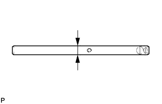
| 16. INSPECT 1ST AND 2ND SHIFT FORK SHAFT |
Using a micrometer, measure the shaft diameter.
- Standard diameter:
- 13.982 to 14.00 mm (0.5505 to 0.5512 in.)
- Minimum diameter:
- 13.982 mm (0.5505 in.)
If the diameter is less than the minimum, replace the 1st and 2nd shift fork shaft.
| 17. INSPECT 3RD AND 4TH SHIFT FORK SHAFT |
Using a micrometer, measure the shaft diameter.
- Standard diameter:
- 13.982 to 14.00 mm (0.5505 to 0.5512 in.)
- Minimum diameter:
- 13.982 mm (0.5505 in.)
If the diameter is less than the minimum, replace the 3rd and 4th shift fork shaft.
| 18. INSPECT 5TH AND 6TH SHIFT FORK SHAFT |
Using a micrometer, measure the shaft diameter.
- Standard diameter:
- 13.982 to 14.00 mm (0.5505 to 0.5512 in.)
- Minimum diameter:
- 13.982 mm (0.5505 in.)
If the diameter is less than the minimum, replace the 5th and 6th shift fork shaft.
| 19. INSPECT REVERSE SHIFT FORK SHAFT |
Using a micrometer, measure the shaft diameter.
- Standard diameter:
- 13.982 to 14.00 mm (0.5505 to 0.5512 in.)
- Minimum diameter:
- 13.982 mm (0.5505 in.)
If the diameter is less than the minimum, replace the reverse shift fork shaft.
| 20. INSPECT NO. 5 GEAR SHIFT FORK SHAFT |
Using a micrometer, measure the shaft diameter.
- Standard diameter:
- 15.966 to 15.984 mm (0.6289 to 0.6293 in.)
- Minimum diameter:
- 15.966 mm (0.6289 in.)
If the diameter is less than the minimum, replace the No. 5 gear shift fork shaft.
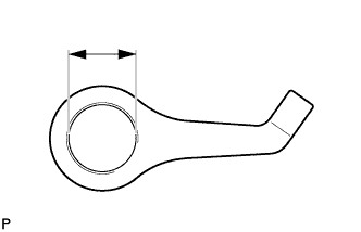
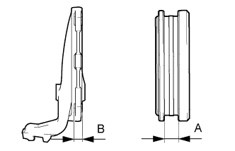
| 21. INSPECT NO. 1 GEAR SHIFT FORK |
Using vernier calipers, measure the thickness and inside diameter.
- Standard inside diameter and thickness:
- A:
- 9.50 to 9.80 mm (0.3740 to 0.3858 in.)
- B:
- 14.010 to 14.043 mm (0.5516 to 0.5529 in.)
If the thickness or inside diameter is out of the specifications, replace the No. 1 gear shift fork.
| 22. INSPECT NO. 2 GEAR SHIFT FORK |
Using vernier calipers, measure the thickness and inside diameter.
- Standard inside diameter and thickness:
- A:
- 9.50 to 9.80 mm (0.3740 to 0.3858 in.)
- B:
- 14.010 to 14.043 mm (0.5516 to 0.5529 in.)
- C:
- 14.70 to 15.30 mm (0.5787 to 0.6024 in.)
If the thickness or inside diameter is out of the specifications, replace the No. 2 gear shift fork.
| 23. INSPECT NO. 3 GEAR SHIFT FORK |
Using vernier calipers, measure the thickness and inside diameter.
- Standard inside diameter and thickness:
- A:
- 9.50 to 9.80 mm (0.3740 to 0.3858 in.)
- B:
- 14.010 to 14.043 mm (0.5516 to 0.5529 in.)
If the thickness or inside diameter is out of the specifications, replace the No. 3 gear shift fork.
| 24. INSPECT REVERSE SHIFT FORK |
Using vernier calipers, measure the thickness and inside diameter.
- Standard inside diameter and thickness:
- A:
- 4.40 to 4.56 mm (0.1732 to 0.1795 in.)
- B:
- 14.010 to 14.043 mm (0.5516 to 0.5529 in.)
- C:
- 14.7 to 15.3 mm (0.5787 to 0.6024 in.)
If the thickness or inside diameter is out of the specifications, replace the reverse shaft fork.
| 25. INSPECT NO. 2 GEAR SHIFT HEAD |
Using vernier calipers, measure the inside diameter.
- Standard inside diameter:
- 13.994 to 14.054 mm (0.5509 to 0.5533 in.)
- Maximum inside diameter:
- 13.994 to 14.054 mm (0.5509 to 0.5533 in.)
If the inside diameter exceeds the maximum, replace the No. 2 gear shift head.
| 26. INSPECT NO. 3 GEAR SHIFT HEAD |
Using vernier calipers, measure the inside diameter.
- Standard inside diameter:
- A:
- 15.994 to 16.054 mm (0.6297 to 0.6320 in.)
- B:
- 14.20 to 14.25 mm (0.5591 to 0.5610 in.)
- Maximum inside diameter:
- A:
- 15.994 to 16.054 mm (0.6297 to 0.6320 in.)
- B:
- 14.20 to 14.25 mm (0.5591 to 0.5610 in.)
If the inside diameter exceeds the maximum, replace the No. 3 gear shift head.
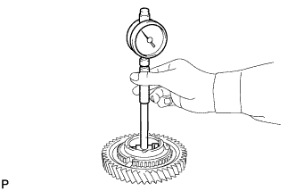
| 27. INSPECT 1ST DRIVEN GEAR |
Using a cylinder gauge, measure the inside diameter.
- Standard inside diameter:
- 53.015 to 53.040 mm (2.0872 to 2.0882 in.)
- Maximum inside diameter:
- 53.040 mm (2.0882 in.)
If the inside diameter exceeds the maximum, replace the 1st driven gear.
| 28. INSPECT 2ND DRIVEN GEAR |
Using a cylinder gauge, measure the inside diameter.
- Standard inside diameter:
- 56.015 to 56.030 mm (2.0872 to 2.0878 in.)
- Maximum inside diameter:
- 56.030 mm (2.0878 in.)
If the inside diameter exceeds the maximum, replace the 2nd driven gear.
| 29. INSPECT 3RD DRIVEN GEAR |
Using a cylinder gauge, measure the inside diameter.
- Standard inside diameter:
- 42.015 to 42.040 mm (1.6541 to 1.6551 in.)
- Maximum inside diameter:
- 42.040 mm (1.6551 in.)
If the inside diameter exceeds the maximum, replace the 3rd driven gear.
| 30. INSPECT 4TH DRIVEN GEAR |
Using a cylinder gauge, measure the inside diameter.
- Standard inside diameter:
- 48.015 to 48.040 mm (1.8904 to 1.8913 in.)
- Maximum inside diameter:
- 48.040 mm (1.8913 in.)
If the inside diameter exceeds the maximum, replace the 4th driven gear.
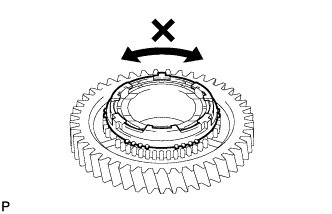
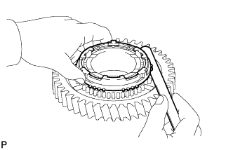
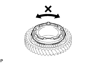
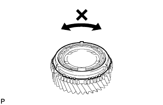
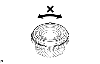
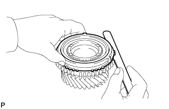
| 31. INSPECT 1ST DRIVEN GEAR SYNCHRONIZER RING SET |
Coat the 1st driven gear with gear oil.
Check that the synchronizer ring does not turn when the ring is pushed to the 1st driven gear.
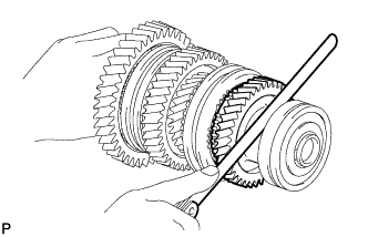
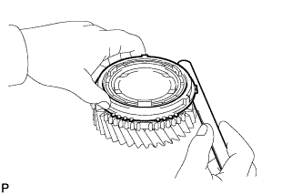
Using a feeler gauge, measure the clearance between the synchronizer ring back and the 1st gear spline end.
- Standard clearance:
- 0.98 to 1.82 mm (0.0386 to 0.0716 in.)
- Minimum clearance:
- 0.98 mm (0.0386 in.)
If the clearance is below the minimum, replace the 1st driven gear synchronizer ring set.
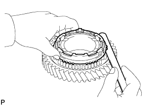
| 32. INSPECT 2ND DRIVEN GEAR SYNCHRONIZER RING SET |
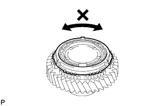
Coat the 2nd driven gear with gear oil.
Check that the synchronizer ring does not turn when the ring is pushed to the 2nd driven gear.
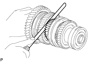
Using a feeler gauge, measure the clearance between the synchronizer ring back and the 2nd gear spline end.
- Standard clearance:
- 1.08 to 1.92 mm (0.0425 to 0.0756 in.)
- Minimum clearance:
- 1.08 mm (0.0425 in.)
If the clearance is below the minimum, replace the 2nd driven gear synchronizer ring set.
| 33. INSPECT 3RD DRIVEN GEAR SYNCHRONIZER RING SET |
Coat the 3rd driven gear with gear oil.
Check that the synchronizer ring does not turn when the ring is pushed to the 3rd driven gear.
Using a feeler gauge, measure the clearance between the 3rd gear synchronizer ring back and the spline end.
- Standard clearance:
- 1.00 to 2.00 mm (0.0394 to 0.0787 in.)
- Minimum clearance:
- 1.00 mm (0.0394 in.)
If the clearance is below the minimum, replace the 3rd driven gear synchronizer ring.
| 34. INSPECT 4TH DRIVEN GEAR SYNCHRONIZER RING SET |
Coat the 4th driven gear with gear oil.
Check that the synchronizer ring does not turn when the ring is pushed to the 4th driven gear.
Using a feeler gauge, measure the clearance between the 4th gear synchronizer ring back and the spline end.
- Standard clearance:
- 0.92 to 1.88 mm (0.0362 to 0.074 in.)
- Minimum clearance:
- 0.92 mm (0.0362 in.)
If the clearance is below the minimum, replace the 4th driven gear synchronizer ring.
| 35. INSPECT NO. 1 TRANSMISSION HUB SLEEVE |
Using a vernier caliper, measure the clearance between the No. 1 transmission hub sleeve and the No. 1 gear shift fork.
- Standard clearance (A - B):
- 0.10 to 0.50 mm (0.0039 to 0.0197 in.)
If the clearance is out of the specifications, replace the No. 1 transmission hub sleeve and No. 1 gear shift fork.
| 36. INSPECT NO. 2 TRANSMISSION HUB SLEEVE |
Using a vernier caliper, measure the clearance between the No. 2 transmission hub sleeve and the No. 2 gear shift fork.
- Standard clearance (A - B):
- 0.10 to 0.50 mm (0.0039 to 0.0197 in.)
If the clearance is out of the specifications, replace the No. 2 transmission hub sleeve and No. 2 gear shift fork.
| 37. INSPECT NO. 2 OUTPUT SHAFT |
Using a dial indicator, measure the output shaft runout.
- Maximum runout:
- 0.03 mm (0.0012 in.)
If the runout exceeds the maximum, replace the No. 2 output shaft.
Using a micrometer, measure the outer diameter of the No. 2 output shaft journal surface.
- Standard diameter:
Measured Part
| Specified Condition
|
A
| 32.002 to 32.018 mm (1.2599 to 1.2605 in.)
|
B
| 35.984 to 36.000 mm (1.4167 to 1.4173 in.)
|
C
| 41.984 to 42.000 mm (1.6529 to 1.6535 in.)
|
D
| 46.984 to 47.000 mm (1.8498 to 1.8504 in.)
|
E
| 35.002 to 35.018 mm (1.3780 to 1.3787 in.)
|
If the diameter is not as specified, replace the No. 2 output shaft.
| 38. INSPECT 5TH DRIVEN GEAR |
Using a cylinder gauge, measure the inside diameter.
- Standard inside diameter:
- 48.015 to 48.040 mm (1.8904 to 1.8913 in.)
- Maximum inside diameter:
- 48.040 mm (1.8913 in.)
If the inside diameter exceeds the maximum, replace the 5th driven gear.
| 39. INSPECT 6TH DRIVEN GEAR |
Using a cylinder gauge, measure the inside diameter.
- Standard inside diameter:
- 42.015 to 42.040 mm (1.6541 to 1.6551 in.)
- Maximum inside diameter:
- 42.040 mm (1.6551 in.)
If the inside diameter exceeds the maximum, replace the 6th driven gear.
| 40. INSPECT REVERSE DRIVEN GEAR |
Using a cylinder gauge, measure the inside diameter.
- Standard inside diameter:
- 53.015 to 53.040 mm (2.0872 to 2.0882 in.)
- Maximum inside diameter:
- 53.040 mm (2.0882 in.)
If the inside diameter exceeds the maximum, replace the reverse driven gear.
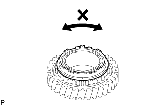
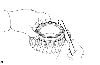
| 41. INSPECT 5TH DRIVEN SYNCHRONIZER RING SET |
Coat the 5th driven gear with gear oil.
Check that the synchronizer ring does not turn when the ring is pushed to the 5th driven gear.
Using a feeler gauge, measure the clearance between the synchronizer ring back and the 5th driven gear spline end.
- Standard clearance:
- 0.80 to 1.60 mm (0.0315 to 0.063 in.)
- Minimum clearance:
- 0.80 mm (0.0315 in.)
If the clearance is below the minimum, replace the 5th driven gear synchronizer ring.
| 42. INSPECT 6TH DRIVEN SYNCHRONIZER RING SET |
Coat the 6th driven gear with gear oil.
Check that the synchronizer ring does not turn when the ring is pushed to the 6th driven gear.
Using a feeler gauge, measure the clearance between the gear synchronizer ring back and the 6th driven gear spline end.
- Standard clearance:
- 0.80 to 1.60 mm (0.0315 to 0.063 in.)
- Minimum clearance:
- 0.80 mm (0.0315 in.)
If the clearance is below the minimum, replace the 6th driven gear synchronizer ring.
| 43. INSPECT REVERSE DRIVEN SYNCHRONIZER RING SET |
Coat the reverse driven gear with gear oil.
Check that the synchronizer ring does not turn when the ring is pushed to the reverse driven gear.
Using a feeler gauge, measure the clearance between the synchronizer ring back and the reverse driven gear spline end.
- Standard clearance:
- 0.68 to 1.32 mm (0.0268 to 0.052 in.)
- Minimum clearance:
- 0.68 mm (0.0268 in.)
If the clearance is below the minimum, replace the reverse driven gear synchronizer ring.
| 44. INSPECT NO. 3 TRANSMISSION HUB SLEEVE |
Using a vernier caliper, measure the clearance between the No. 3 transmission hub sleeve and the No. 3 gear shift fork.
- Standard clearance (A - B):
- 0.10 to 0.50 mm (0.0039 to 0.0197 in.)
If the clearance is out of the specifications, replace the No. 3 transmission hub sleeve and No. 3 gear shift fork.
| 45. INSPECT NO. 4 TRANSMISSION HUB SLEEVE |
Using a vernier calipers, measure the clearance between the No. 4 transmission hub sleeve and the reverse shift fork.
- Standard clearance (A - B):
- 0.15 to 0.41 mm (0.0059 to 0.0161 in.)
If the clearance is out of the specifications, replace the No. 4 transmission hub sleeve and reverse shift fork.