Dtc P0340 Camshaft Position Sensor A Circuit (Bank 1 Or Single Sensor)
DESCRIPTION
WIRING DIAGRAM
INSPECTION PROCEDURE
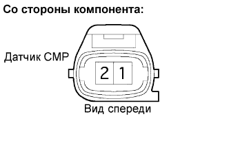
INSPECT CAMSHAFT POSITION SENSOR (RESISTANCE)
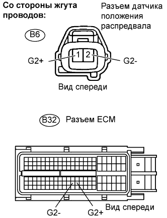
CHECK HARNESS AND CONNECTOR (CAMSHAFT POSITION SENSOR - ECM)
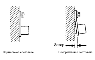
CHECK SENSOR INSTALLATION (CAMSHAFT POSITION SENSOR)
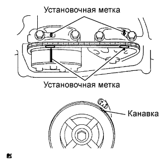
CHECK VALVE TIMING
CHECK CAMSHAFT
REPLACE CAMSHAFT POSITION SENSOR
CHECK AND REPLACE WHETHER DTC OUTPUT RECURS
DTC P0340 Camshaft Position Sensor "A" Circuit (Bank 1 or Single Sensor) |
DESCRIPTION
The Camshaft Position (CMP) sensor consists of a magnet and an iron core which is wrapped with copper wire, and is installed onto the cylinder head. When the camshaft rotates, each of 3 teeth on the camshaft passes through the CMP sensor. This activates the internal magnet in the sensor, generating a voltage in the copper wire. The camshaft rotation is synchronized with the crankshaft rotation. When the crankshaft turns twice, the voltage is generated 3 times in the CMP sensor. The generated voltage in the sensor acts as a signal, allowing the ECM to locate the camshaft position. This signal is then used to control ignition timing, fuel injection timing, and the VVT system.DTC No.
| DTC Detection Condition
| Trouble Area
|
P0340
| Case 1
- No Camshaft Position (CMP) sensor signal to ECM while cranking (2 trip detection logic)
Case 2
- Camshaft/Crankshaft misalignment detected at engine speed of 600 rpm or more (1 trip detection logic)
| - Open or short in CMP sensor circuit
- CMP sensor
- Camshaft
- Jumped tooth of timing chain
- ECM
|
- УКАЗАНИЕ:
- DTC P0340 indicates a malfunction relating to the CMP sensor (+) circuit (the wire harness between the ECM and CMP sensor, and the CMP sensor itself).
Reference: Inspection using an oscilloscope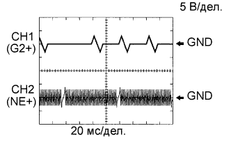
- УКАЗАНИЕ:
- The correct waveform is as shown in the illustration.
- G2+ stands for the CMP sensor signal, and NE+ stands for the Crankshaft Position (CKP) sensor signal.
- Grounding failure of the shielded wire may cause noise in waveforms.
Item
| Content
|
Terminals
| CH1: G2+ - G2-
CH2: NE+ - NE-
|
Equipment Settings
| 5 V/DIV.
20 ms./DIV.
|
Conditions
| Cranking or idling
|
WIRING DIAGRAM
Refer to DTC P0335 (see page RAV4_ACA30 RM000000TCW01KX_07.html).
INSPECTION PROCEDURE
- УКАЗАНИЕ:
- Read freeze frame data using the intelligent tester. Freeze frame data records the engine condition when malfunctions are detected. When troubleshooting, freeze frame data can help determine if the vehicle was moving or stationary, if the engine was warmed up or not, if the air-fuel ratio was lean or rich, and other data from the time the malfunction occurred.
| 1.INSPECT CAMSHAFT POSITION SENSOR (RESISTANCE) |
Disconnect the B6 Camshaft Position (CMP) sensor connector.
Measure the resistance between terminals 1 and 2.
- Standard resistance:
Tester Connection
| Condition
| Specified Condition
|
1 - 2
| Cold
| 1,630 to 2,740 Ω
|
1 - 2
| Hot
| 2,065 to 3,225 Ω
|
- УКАЗАНИЕ:
- Terms cold and hot refer to the temperature of the sensor. Cold means approximately -10 to 50°C (14 to 122°F). Hot means approximately 50 to 100°C (122 to 212°F).
Reconnect the CMP sensor connector.
| | REPLACE CAMSHAFT POSITION SENSOR |
|
|
| 2.CHECK HARNESS AND CONNECTOR (CAMSHAFT POSITION SENSOR - ECM) |
Disconnect the B6 CMP sensor connector.
Disconnect the B32 ECM connector.
Measure the resistance.
- Standard resistance (Check for open):
Tester Connection
| Specified Condition
|
G2+ (B6-1) - G2+ (B32-99)
| Below 1 Ω
|
G2- (B6-2) - G2- (B32-98)
|
- Standard resistance (Check for short):
Tester Connection
| Specified Condition
|
G2+ (B6-1) or G2+ (B32-99) - Body ground
| 10 kΩor higher
|
G2- (B6-2) or G2- (B32-98) - Body ground
|
Reconnect the ECM connector.
Reconnect the CMP sensor connector.
| | REPAIR OR REPLACE HARNESS OR CONNECTOR |
|
|
| 3.CHECK SENSOR INSTALLATION (CAMSHAFT POSITION SENSOR) |
Check the CMP sensor installation.
- OK:
- Sensor is installed correctly.
| | SECURELY REINSTALL SENSOR |
|
|
Remove the cylinder head cover.
Turn the crankshaft pulley, and align its groove with the timing mark "0" on the timing chain cover.
Check that the timing marks on the camshaft timing sprocket and camshaft timing gear are facing upward as shown in the illustration.
- If not, turn the crankshaft 1 revolution (360°), then align the marks as above.
- OK:
- Timing marks on camshaft timing gears are aligned as shown in the illustration.
Reinstall the cylinder head cover.
Check the teeth of the camshaft.
- OK:
- Camshaft teeth do not have any cracks or deformation.
| 6.REPLACE CAMSHAFT POSITION SENSOR |
| 7.CHECK AND REPLACE WHETHER DTC OUTPUT RECURS |
Connect the intelligent tester to the DLC3.
Turn the ignition switch on (IG) and turn the tester ON.
Clear DTCs (see page RAV4_ACA30 RM000000PDK013X.html).
Start the engine.
Select the following menu items: Powertrain / Engine and ECT / DTC.
Read DTCs.
- Result:
Display (DTC Output)
| Proceed to
|
No output
| A
|
P0340
| B
|
- УКАЗАНИЕ:
- If the engine does not start, replace the ECM.