Топливная Форсунка -- Установка |
| 1. INSTALL NOZZLE HOLDER AND NOZZLE SET |
Install 4 new injection nozzle seat gaskets and the 4 injection nozzle seats to the injection nozzle holes of the cylinder head.
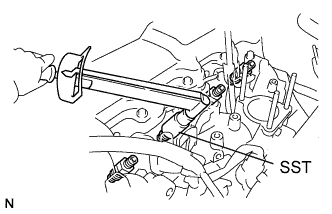 |
Using SST, install the 4 nozzle holder and nozzle sets.
- SST
- 09268-64010(09268-64020)
- Момент затяжки:
- 64 N*m{650 kgf*cm, 47 ft.*lbf}
| 2. INSTALL NOZZLE LEAKAGE PIPE ASSEMBLY |
Install 4 new ring packing washers and the leakage pipe with the 4 nuts.
- Момент затяжки:
- 30 N*m{301 kgf*cm, 22 ft.*lbf}
Connect the fuel hose to the leakage pipe.
| 3. INSTALL NO. 1 GLOW PLUG CONNECTOR |
Install the No. 1 glow plug resistor insulator and No. 1 glow plug connector.
Install the glow plug connector with the 4 nuts. Uniformly tighten the nuts.
- Момент затяжки:
- 1.0 N*m{10 kgf*cm, 9 in.*lbf}
Text in Illustration *1 Nut *2 Washer *3 No. 2 Glow Plug Resistor Insulator *4 Engine Wire *5 No. 1 Glow Plug Connector *6 No. 1 Glow Plug Resistor Insulator *7 Bolt
 |
Install the 4 screw grommets.
Connect the engine wire and install the No. 2 glow plug resistor insulator and washer with the bolt.
- Момент затяжки:
- 5.0 N*m{51 kgf*cm, 44 in.*lbf}
| 4. INSTALL INJECTION PIPE SET |
Install the 2 lower clamps to the intake manifold.
Install the 4 injection pipes.
- Момент затяжки:
- 25 N*m{250 kgf*cm, 18 ft.*lbf}
Text in Illustration *a for Injection Nozzle Side *b for Injection Pump Side - ПРИМЕЧАНИЕ:
- Use the formula to calculate special torque values for situations where a union nut wrench is combined with a torque wrench (See page Нажмите здесь).
 |
Install the 2 upper pipe clamps with the 2 nuts.
- Момент затяжки:
- 5.0 N*m{51 kgf*cm, 44 in.*lbf}
| 5. INSTALL DIESEL THROTTLE BODY |
Install the diesel throttle body (See page Нажмите здесь).
| 6. CONNECT CABLE TO NEGATIVE BATTERY TERMINAL |
- ПРИМЕЧАНИЕ:
- When disconnecting the cable, some systems need to be initialized after the cable is reconnected (See page Нажмите здесь).
| 7. BLEED INJECTION PIPE |
Move the hand pump on the upper part of the fuel filter up and down and fill the injection pump and fuel system with fuel.
Loosen one of the union nuts (on the nozzle side).
Crank the engine until fuel comes out from the union nut connection (on the nozzle side).
Tighten the union nut.
- Момент затяжки:
- 25 N*m{250 kgf*cm, 18 ft.*lbf}
- ПРИМЕЧАНИЕ:
- Use the formula to calculate special torque values for situations where a union nut wrench is combined with a torque wrench (See page Нажмите здесь).
Perform the procedures above for each injection pipe.
| 8. INSPECT FOR FUEL LEAK |
Check that there are no fuel leaks anywhere in the fuel system after performing maintenance.
- УКАЗАНИЕ:
- When checking for fuel leaks, make sure that there is pressure in the fuel line.