Двигатель. COROLLA, AURIS. ZZE150 ZRE151,152 NDE150
DESCRIPTION
INSPECTION PROCEDURE
PERFORM ACTIVE TEST BY INTELLIGENT TESTER (OPERATE ELECTRIC COOLING FAN)
INSPECT ECM (FANL AND FANH VOLTAGE)
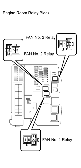
INSPECT ENGINE ROOM RELAY BLOCK (FAN NO. 1 RELAY AND FAN NO. 3 RELAY VOLTAGE)
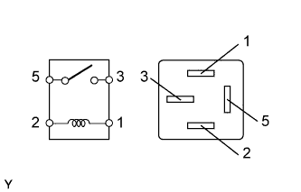
INSPECT FAN NO. 1 RELAY
INSPECT FAN NO. 2 RELAY
INSPECT FAN NO. 3 RELAY
CHECK HARNESS AND CONNECTOR (ENGINE ROOM RELAY BLOCK - BODY GROUND)
INSPECT RADIATOR FAN MOTOR
CHECK HARNESS AND CONNECTOR (RADIATOR FAN MOTOR - BODY GROUND)
CHECK HARNESS AND CONNECTOR (RADIATOR FAN MOTOR - ENGINE ROOM RELAY BLOCK)
INSPECT AIR CONDITIONER CONDENSER FAN MOTOR
CHECK HARNESS AND CONNECTOR (A/C CONDENSER FAN MOTOR - ENGINE ROOM RELAY BLOCK)
INSPECT ENGINE ROOM RELAY BLOCK (FAN NO. 1 RELAY - FAN NO. 2 RELAY)
CHECK FUSE (ECU-IG NO. 1 FUSE)
CHECK FUSE (ECU-IG NO. 1 FUSE VOLTAGE)
INSPECT FAN NO. 1 RELAY
INSPECT FAN NO. 2 RELAY
INSPECT FAN NO. 3 RELAY
CHECK HARNESS AND CONNECTOR (ENGINE ROOM RELAY BLOCK - ECM)
CHECK HARNESS AND CONNECTOR (ECU-IG NO. 1 FUSE - ENGINE ROOM RELAY BLOCK)
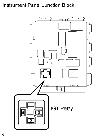
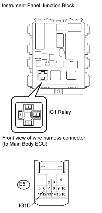
INSPECT IG1 RELAY
INSPECT INSTRUMENT PANEL JUNCTION BLOCK (IG1 RELAY VOLTAGE)
CHECK HARNESS AND CONNECTOR (IG1 RELAY - BODY GROUND)
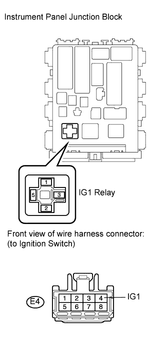
CHECK HARNESS AND CONNECTOR (IG1 RELAY - IGNITION SWITCH)
CHECK HARNESS AND CONNECTOR (IG1 RELAY - MAIN BODY ECU)
ВЕНТИЛЯТОР СИСТЕМЫ ОХЛАЖДЕНИЯ - Цепь вентилятора системы охлаждения |
DESCRIPTION
The ECM turns on or off the fan relays using signals calculated from the engine coolant temperature, air conditioning (ON/OFF), air conditioner refrigerant pressure, engine speed, and vehicle speed signals.The ECM switches the circuit of the cooling fan motors between series and parallel by turning on or off the fan relays in order to control the speed of the cooling fan motors in two steps.
INSPECTION PROCEDURE
- ПРИМЕЧАНИЕ:
- After replacing the ECM, the new ECM needs registration (See page Нажмите здесь) and initialization (See page Нажмите здесь).
| 1.PERFORM ACTIVE TEST BY INTELLIGENT TESTER (OPERATE ELECTRIC COOLING FAN) |
Connect the intelligent tester to the DLC3.
Turn the ignition switch on (IG).
Turn the tester on.
Enter the following menu items: Powertrain / Engine and ECT / Active Test / Control the Electric Cooling Fan.
- OK:
Tester Operation
| Specified Condition
|
ON
| Fan rotates
|
OFF
| Fan does not rotate
|
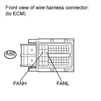
| 2.INSPECT ECM (FANL AND FANH VOLTAGE) |
Disconnect the ECM connector.
Turn the ignition switch on (IG).
Measure the voltage according to the value(s) in the table below.
- Standard voltage:
Tester Connection
| Switch Condition
| Specified Condition
|
A50-21 (FANH) - Body ground
| Ignition switch on (IG)
| 11 to 14 V
|
A50-22 (FANL) - Body ground
| Ignition switch on (IG)
| 11 to 14 V
|
Reconnect the ECM connector.
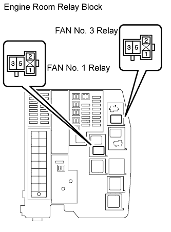
| 3.INSPECT ENGINE ROOM RELAY BLOCK (FAN NO. 1 RELAY AND FAN NO. 3 RELAY VOLTAGE) |
Remove the FAN No. 1 relay and FAN No. 3 relay from the engine room relay block.
Measure the voltage according to the value(s) in the table below.
- Standard voltage:
Tester Connection
| Condition
| Specified Condition
|
3 (FAN No. 1 relay) - Body ground
| Always
| 11 to 14 V
|
5 (FAN No. 3 relay) - Body ground
| Always
| 11 to 14 V
|
Reinstall the FAN No. 1 relay and FAN No. 3 relay.
| | REPAIR OR REPLACE HARNESS OR CONNECTOR (BATTERY - ENGINE ROOM RELAY BLOCK) |
|
|
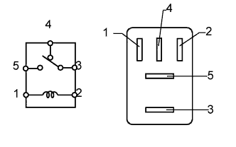
| 4.INSPECT FAN NO. 1 RELAY |
Remove the FAN No. 1 relay from the engine room relay block.
Measure the resistance according to the value(s) in the table below.
- Standard resistance:
Tester Connection
| Condition
| Specified Condition
|
3 - 5
| Voltage is not applied between terminals 1 and 2
| 10 kΩ or higher
|
Voltage is applied between terminals 1 and 2
| Below 1 Ω
|
Reinstall the FAN No. 1 relay.
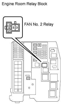
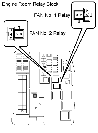
| 5.INSPECT FAN NO. 2 RELAY |
Remove the FAN No. 2 relay from the engine room relay block.
Measure the resistance according to the value(s) in the table below.
- Standard resistance:
Tester Connection
| Condition
| Specified Condition
|
3 - 4
| Voltage is not applied between terminals 1 and 2
| Below 1 Ω
|
Voltage is applied between terminals 1 and 2
| 10 kΩ or higher
|
3 - 5
| Voltage is not applied between terminals 1 and 2
| 10 kΩ or higher
|
Voltage is applied between terminals 1 and 2
| Below 1 Ω
|
Reinstall the FAN No. 2 relay.
| 6.INSPECT FAN NO. 3 RELAY |
Remove the FAN No. 3 relay from the engine room relay block.
Measure the resistance according to the value(s) in the table below.
- Standard resistance:
Tester Connection
| Condition
| Specified Condition
|
3 - 5
| Voltage is not applied between terminals 1 and 2
| 10 kΩ or higher
|
Voltage is applied between terminals 1 and 2
| Below 1 Ω
|
Reinstall the FAN No. 3 relay.
| 7.CHECK HARNESS AND CONNECTOR (ENGINE ROOM RELAY BLOCK - BODY GROUND) |
Remove the FAN No. 2 relay from the engine room relay block.
Measure the resistance according to the value(s) in the table below.
- Standard resistance:
Tester Connection
| Condition
| Specified Condition
|
5 (FAN No. 2 relay) - Body ground
| Always
| Below 1 Ω
|
Reinstall the FAN No. 2 relay.
| | REPAIR OR REPLACE HARNESS OR CONNECTOR (ENGINE ROOM RELAY BLOCK - BODY GROUND) |
|
|
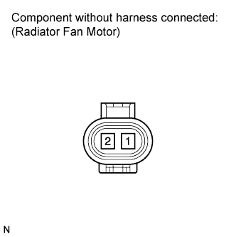
| 8.INSPECT RADIATOR FAN MOTOR |
Disconnect the radiator fan motor connector.
Check that the radiator fan motor turns smoothly when the battery is connected to the radiator fan motor connector.
Measure the current while the motor is turning.
- Standard current:
- 11.2 to 14.5 A
Reconnect the radiator fan motor connector.
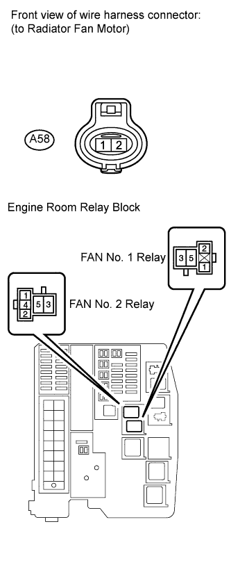
| 9.CHECK HARNESS AND CONNECTOR (RADIATOR FAN MOTOR - BODY GROUND) |
Disconnect the radiator fan motor connector.
Measure the resistance according to the value(s) in the table below.
- Standard resistance:
Tester Connection
| Condition
| Specified Condition
|
A58-1 - Body ground
| Always
| Below 1 Ω
|
Reconnect the radiator fan motor connector.
| | REPAIR OR REPLACE HARNESS OR CONNECTOR (RADIATOR FAN MOTOR - BODY GROUND) |
|
|
| 10.CHECK HARNESS AND CONNECTOR (RADIATOR FAN MOTOR - ENGINE ROOM RELAY BLOCK) |
Disconnect the radiator fan motor connector.
Remove the FAN No. 1 relay and FAN No. 2 relay from the engine room relay block.
Measure the resistance according to the value(s) in the table below.
- Standard resistance (Check for open):
Tester Connection
| Condition
| Specified Condition
|
A58-2 - 5 (FAN No. 1 relay)
| Always
| Below 1 Ω
|
A58-2 - 4 (FAN No. 2 relay)
| Always
| Below 1 Ω
|
- Standard resistance (Check for short):
Tester Connection
| Condition
| Specified Condition
|
A58-2 or 5 (FAN No. 1 relay) - Body ground
| Always
| 10 kΩ or higher
|
A58-2 or 4 (FAN No. 2 relay) - Body ground
| Always
| 10 kΩ or higher
|
Reconnect the radiator fan motor connector.
Reinstall the FAN No. 1 relay and FAN No. 2 relay.
| | REPAIR OR REPLACE HARNESS OR CONNECTOR (RADIATOR FAN MOTOR - ENGINE ROOM RELAY BLOCK) |
|
|
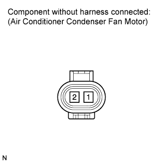
| 11.INSPECT AIR CONDITIONER CONDENSER FAN MOTOR |
Disconnect the air conditioner condenser fan motor connector.
Check that the air conditioner condenser fan motor turns smoothly when the battery is connected to the air conditioner condenser fan motor connector.
Measure the current while the motor is turning.
- Standard current:
- 7.4 to 10.9 A
Reconnect the air conditioner condenser fan motor connector.
| | REPLACE AIR CONDITIONER CONDENSER FAN MOTOR |
|
|
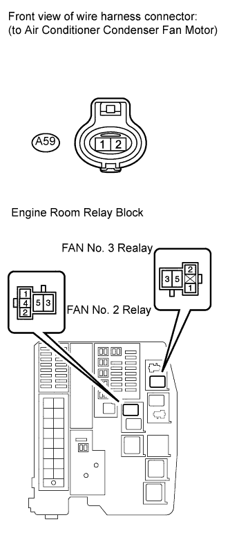
| 12.CHECK HARNESS AND CONNECTOR (A/C CONDENSER FAN MOTOR - ENGINE ROOM RELAY BLOCK) |
Disconnect the Air Conditioner (A/C) condenser fan motor connector.
Remove the FAN No. 2 relay and FAN No. 3 relay from the engine room relay block.
Measure the resistance according to the value(s) in the table below.
- Standard resistance (Check for open):
Tester Connection
| Condition
| Specified Condition
|
A59-1 - 3 (FAN No. 2 relay)
| Always
| Below 1 Ω
|
A59-2 - 3 (FAN No. 3 relay)
| Always
| Below 1 Ω
|
- Standard resistance (Check for short):
Tester Connection
| Condition
| Specified Condition
|
A59-1 or 3 (FAN No. 2 relay) - Body ground
| Always
| 10 kΩ or higher
|
A59-2 or 3 (FAN No. 3 relay) - Body ground
| Always
| 10 kΩ or higher
|
Reconnect the air conditioner condenser fan motor connector.
Reinstall the FAN No. 2 relay and FAN No. 3 relay.
| | REPAIR OR REPLACE HARNESS OR CONNECTOR (A/C CONDENSER FAN MOTOR - ENGINE ROOM RELAY BLOCK) |
|
|
| 13.INSPECT ENGINE ROOM RELAY BLOCK (FAN NO. 1 RELAY - FAN NO. 2 RELAY) |
Remove the FAN No. 1 relay and FAN No. 2 relay from the engine room relay block.
Measure the resistance according to the value(s) in the table below.
- Standard resistance (Check for open):
Tester Connection
| Condition
| Specified Condition
|
1 (FAN No. 1 relay) - 1 (FAN No. 2 relay)
| Always
| Below 1 Ω
|
2 (FAN No. 1 relay) - 2 (FAN No. 2 relay)
| Always
| Below 1 Ω
|
- Standard resistance (Check for short):
Tester Connection
| Condition
| Specified Condition
|
1 (FAN No. 1 relay) or 1 (FAN No. 2 relay) - Body ground
| Always
| 10 kΩ or higher
|
2 (FAN No. 1 relay) or 2 (FAN No. 2 relay) - Body ground
| Always
| 10 kΩ or higher
|
Reinstall the FAN No. 1 relay and FAN No. 2 relay.
| | REPLACE ENGINE ROOM RELAY BLOCK |
|
|
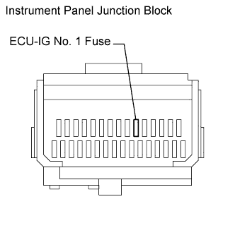
| 14.CHECK FUSE (ECU-IG NO. 1 FUSE) |
Remove the ECU-IG No. 1 fuse from the instrument panel junction block.
Measure the resistance according to the value(s) in the table below.
- Standard resistance:
Tester Connection
| Condition
| Specified Condition
|
ECU-IG No. 1 fuse
| Always
| Below 1 Ω
|
Reinstall the ECU-IG No. 1 fuse.
| | REPLACE FUSE (ECU-IG NO. 1 FUSE) |
|
|
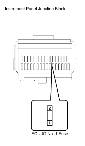
| 15.CHECK FUSE (ECU-IG NO. 1 FUSE VOLTAGE) |
Remove the ECU-IG No. 1 fuse from the instrument panel junction block.
Turn the ignition switch on (IG).
Measure the voltage according to the value(s) in the table below.
- Standard voltage:
Tester Connection
| Switch Condition
| Specified Condition
|
1 (ECU-IG No. 1 fuse) - Body ground
| Ignition switch on (IG)
| 11 to 14 V
|
Reinstall the ECU-IG No. 1 fuse.
| 16.INSPECT FAN NO. 1 RELAY |
Remove the FAN No. 1 relay from the engine room relay block.
Measure the resistance according to the value(s) in the table below.
- Standard resistance:
Tester Connection
| Condition
| Specified Condition
|
3 - 5
| Voltage is not applied between terminals 1 and 2
| 10 kΩ or higher
|
Voltage is applied between terminals 1 and 2
| Below 1 Ω
|
Reinstall the FAN No. 1 relay.
| 17.INSPECT FAN NO. 2 RELAY |
Remove the FAN No. 2 relay from the engine room relay block.
Measure the resistance according to the value(s) in the table below.
- Standard resistance:
Tester Connection
| Condition
| Specified Condition
|
3 - 4
| Voltage is not applied between terminals 1 and 2
| Below 1 Ω
|
Voltage is applied between terminals 1 and 2
| 10 kΩ or higher
|
3 - 5
| Voltage is not applied between terminals 1 and 2
| 10 kΩ or higher
|
Voltage is applied between terminals 1 and 2
| Below 1 Ω
|
Reinstall the FAN No. 2 relay.
| 18.INSPECT FAN NO. 3 RELAY |
Remove the FAN No. 3 relay from the engine room relay block.
Measure the resistance according to the value(s) in the table below.
- Standard resistance:
Tester Connection
| Condition
| Specified Condition
|
3 - 5
| Voltage is not applied between terminals 1 and 2
| 10 kΩ or higher
|
Voltage is applied between terminals 1 and 2
| Below 1 Ω
|
Reinstall the FAN No. 3 relay.
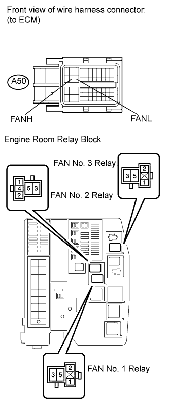
| 19.CHECK HARNESS AND CONNECTOR (ENGINE ROOM RELAY BLOCK - ECM) |
Remove the FAN No. 1 relay, FAN No. 2 relay and FAN No. 3 relay from the engine room relay block.
Disconnect the ECM connector.
Measure the resistance according to the value(s) in the table below.
- Standard resistance (Check for open):
Tester Connection
| Condition
| Specified Condition
|
2 (FAN No. 1 relay) - A50-21 (FANH)
| Always
| Below 1 Ω
|
2 (FAN No. 2 relay) - A50-21 (FANH)
| Always
| Below 1 Ω
|
2 (FAN No. 3 relay) - A50-22 (FANL)
| Always
| Below 1 Ω
|
- Standard resistance (Check for short):
Tester Connection
| Condition
| Specified Condition
|
2 (FAN No. 1 relay) or A50-21 (FANH) - Body ground
| Always
| 10 kΩ or higher
|
2 (FAN No. 2 relay) or A50-21 (FANH) - Body ground
| Always
| 10 kΩ or higher
|
2 (FAN No. 3 relay) or A50-22 (FANL) - Body ground
| Always
| 10 kΩ or higher
|
Reinstall the FAN No. 1 relay, FAN No. 2 relay and FAN No. 3 relay.
Reconnect the ECM connector.
| | REPAIR OR REPLACE HARNESS OR CONNECTOR (ENGINE ROOM RELAY BLOCK - ECM) |
|
|
| 20.CHECK HARNESS AND CONNECTOR (ECU-IG NO. 1 FUSE - ENGINE ROOM RELAY BLOCK) |
Remove the FAN No. 1 relay, FAN No. 2 relay and FAN No. 3 relay from the engine room relay block.
Remove the ECU-IG No. 1 fuse from the instrument panel junction block.
Measure the resistance according to the value(s) in the table below.
- Standard resistance (Check for open):
Tester Connection
| Condition
| Specified Condition
|
1 (FAN No. 1 relay) - 2 (ECU-IG No. 1 fuse)
| Always
| Below 1 Ω
|
1 (FAN No. 2 relay) - 2 (ECU-IG No. 1 fuse)
| Always
| Below 1 Ω
|
1 (FAN No. 3 relay) - 2 (ECU-IG No. 1 fuse)
| Always
| Below 1 Ω
|
- Standard resistance (Check for short):
Tester Connection
| Condition
| Specified Condition
|
1 (FAN No. 1 relay) or 2 (ECU-IG No. 1 fuse) - Body ground
| Always
| 10 kΩ or higher
|
1 (FAN No. 2 relay) or 2 (ECU-IG No. 1 fuse) - Body ground
| Always
| 10 kΩ or higher
|
1 (FAN No. 3 relay) or 2 (ECU-IG No. 1 fuse) - Body ground
| Always
| 10 kΩ or higher
|
Reinstall the FAN No. 1 relay, FAN No. 2 relay and FAN No. 3 relay.
Reinstall the ECU-IG No. 1 fuse.
| | REPAIR OR REPLACE HARNESS OR CONNECTOR (ECU-IG NO. 1 FUSE - ENGINE ROOM RELAY BLOCK) |
|
|
Remove the IG1 relay from the instrument panel junction block.
Measure the IG1 relay resistance.
- Standard resistance:
Tester Connection
| Condition
| Specified Condition
|
3 - 5
| Voltage is not applied between terminals 1 and 2
| 10 kΩ or higher
|
Voltage is applied between terminals 1 and 2
| Below 1 Ω
|
Reinstall the IG1 relay.
| 22.INSPECT INSTRUMENT PANEL JUNCTION BLOCK (IG1 RELAY VOLTAGE) |
Remove the IG1 relay from the instrument panel junction block.
Measure the voltage according to the value(s) in the table below.
- Standard voltage:
Tester Connection
| Condition
| Specified Condition
|
5 (IG1 relay) - Body ground
| Always
| 11 to 14 V
|
Reinstall the IG1 relay.
| | REPAIR OR REPLACE HARNESS OR CONNECTOR (BATTERY - INSTRUMENT PANEL JUNCTION BLOCK) |
|
|
| 23.CHECK HARNESS AND CONNECTOR (IG1 RELAY - BODY GROUND) |
Remove the IG1 relay from the instrument panel junction block.
Measure the resistance according to the value(s) in the table below.
- Standard resistance:
Tester Connection
| Condition
| Specified Condition
|
1 (IG1 relay) - Body ground
| Always
| Below 1 Ω
|
Reinstall the IG1 relay.
- Result:
Result
| Proceed to
|
OK (w/o Entry and Start System)
| A
|
OK (w/ Entry and Start System)
| B
|
NG
| C
|
| |
|
| | REPAIR OR REPLACE HARNESS OR CONNECTOR (IG1 RELAY - BODY GROUND) |
|
|
| 24.CHECK HARNESS AND CONNECTOR (IG1 RELAY - IGNITION SWITCH) |
Remove the IG1 relay from the instrument panel junction block.
Disconnect the ignition switch connector.
Measure the resistance according to the value(s) in the table below.
- Standard resistance (Check for open):
Tester Connection
| Condition
| Specified Condition
|
E4-4 (IG1) - 2 (IG1 relay)
| Always
| Below 1 Ω
|
- Standard resistance (Check for short):
Tester Connection
| Condition
| Specified Condition
|
E4-4 (IG1) or 2 (IG1 relay) - Body ground
| Always
| 10 kΩ or higher
|
Reinstall the IG1 relay.
Reconnect the ignition switch connector.
| | REPAIR OR REPLACE HARNESS OR CONNECTOR (IG1 RELAY - IGNITION SWITCH) |
|
|
| 25.CHECK HARNESS AND CONNECTOR (IG1 RELAY - MAIN BODY ECU) |
Remove the IG1 relay from the instrument panel junction block.
Disconnect the main body ECU connector.
Measure the resistance according to the value(s) in the table below.
- Standard resistance (Check for open):
Tester Connection
| Condition
| Specified Condition
|
E51-6 (IG1D) - 2 (IG1 relay)
| Always
| Below 1 Ω
|
- Standard resistance (Check for short):
Tester Connection
| Condition
| Specified Condition
|
E51-6 (IG1D) or 2 (IG1 relay) - Body ground
| Always
| 10 kΩ or higher
|
Reinstall the IG1 relay.
Reconnect the main body ECU connector.
| | REPAIR OR REPLACE HARNESS OR CONNECTOR (IG1 RELAY - MAIN BODY ECU) |
|
|