Регулятор Давления В Топливной Системе Снятие. Corolla Auris
Двигатель. COROLLA, AURIS. ZZE150 ZRE151,152 NDE150
REMOVE REAR SEAT CUSHION ASSEMBLY (for Sedan)
REMOVE REAR SEAT HEADREST ASSEMBLY (for Hatchback LH Side)
REMOVE NO. 1 REAR SEAT CUSHION HINGE COVER (for Hatchback LH Side)
REMOVE NO. 2 REAR SEAT CUSHION HINGE COVER (for Hatchback LH Side)
REMOVE REAR SEAT ASSEMBLY LH (for Hatchback)
REMOVE REAR DOOR SCUFF PLATE LH (for Hatchback)
REMOVE REAR SEAT HEADREST ASSEMBLY (for Hatchback RH Side)
REMOVE CENTER REAR SEAT HEADREST ASSEMBLY (for Hatchback)
REMOVE NO. 1 REAR SEAT CUSHION HINGE COVER (for Hatchback RH Side)
REMOVE NO. 2 REAR SEAT CUSHION HINGE COVER (for Hatchback RH Side)
REMOVE REAR SEAT ASSEMBLY RH (for Hatchback)
REMOVE REAR SEAT INNER BELT ASSEMBLY RH (for Hatchback)
REMOVE REAR DOOR SCUFF PLATE RH (for Hatchback)
REMOVE REAR FLOOR SERVICE HOLE COVER
DISCHARGE FUEL SYSTEM PRESSURE
DISCONNECT CABLE FROM NEGATIVE BATTERY TERMINAL
REMOVE FUEL TANK MAIN TUBE SUB-ASSEMBLY
REMOVE NO. 1 FUEL EVAPORATION TUBE SUB-ASSEMBLY
DISCONNECT FUEL TANK EVAPORATION TUBE
DISCONNECT NO. 1 CHARCOAL CANISTER OUTLET HOSE
REMOVE FUEL PUMP GAUGE RETAINER
REMOVE FUEL SUCTION TUBE ASSEMBLY
DRAIN FUEL
REMOVE FUEL SENDER GAUGE ASSEMBLY
REMOVE FUEL PUMP
REMOVE FUEL PRESSURE REGULATOR ASSEMBLY
Регулятор Давления В Топливной Системе -- Снятие |
| 1. REMOVE REAR SEAT CUSHION ASSEMBLY (for Sedan) |
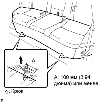
Отцепите 2 передних крепления подушки сиденья от кузова автомобиля.
- ПРИМЕЧАНИЕ:
- Поскольку рама подушки легко деформируется, аккуратно соблюдайте приведенные ниже указания.
Выберите крепление, которое будет отсоединяться первым. Расположите руки рядом с креплением, как показано на рисунке. Затем поднимите подушку сиденья, чтобы отсоединить крепление.
Повторите рассмотренную выше операцию для другого крепления.
Отсоедините 2 задних крепления подушки сиденья от спинки сиденья.
Снимите подушку сиденья.
| 2. REMOVE REAR SEAT HEADREST ASSEMBLY (for Hatchback LH Side) |
| 3. REMOVE NO. 1 REAR SEAT CUSHION HINGE COVER (for Hatchback LH Side) |
- УКАЗАНИЕ:
- See page Нажмите здесь.
| 4. REMOVE NO. 2 REAR SEAT CUSHION HINGE COVER (for Hatchback LH Side) |
- УКАЗАНИЕ:
- See page Нажмите здесь.
| 5. REMOVE REAR SEAT ASSEMBLY LH (for Hatchback) |
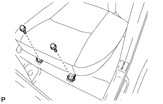
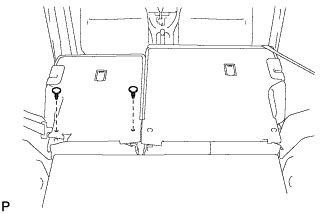
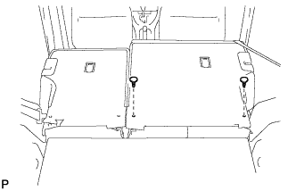
Выверните 2 болта с передней стороны левого заднего сиденья в сборе.
Снимите 2 фиксатора.
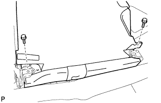
Наклоните левое заднее сиденье в сборе вперед, чтобы вывернуть 2 болта, и снимите левое заднее сиденье в сборе.
- ПРИМЕЧАНИЕ:
- Соблюдайте осторожность, чтобы не повредить кузов автомобиля.
| 6. REMOVE REAR DOOR SCUFF PLATE LH (for Hatchback) |
- УКАЗАНИЕ:
- See page Нажмите здесь.
| 7. REMOVE REAR SEAT HEADREST ASSEMBLY (for Hatchback RH Side) |
| 8. REMOVE CENTER REAR SEAT HEADREST ASSEMBLY (for Hatchback) |
| 9. REMOVE NO. 1 REAR SEAT CUSHION HINGE COVER (for Hatchback RH Side) |
- УКАЗАНИЕ:
- See page Нажмите здесь.
| 10. REMOVE NO. 2 REAR SEAT CUSHION HINGE COVER (for Hatchback RH Side) |
- УКАЗАНИЕ:
- See page Нажмите здесь.
| 11. REMOVE REAR SEAT ASSEMBLY RH (for Hatchback) |
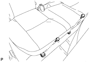
Выверните 2 болта с передней стороны правого заднего сиденья в сборе.
Снимите 2 фиксатора.
Наклоните правое заднее сиденье в сборе вперед, чтобы вывернуть 2 болта на задней части, и снимите правое заднее сиденье в сборе.
- ПРИМЕЧАНИЕ:
- Соблюдайте осторожность, чтобы не повредить кузов автомобиля.
| 12. REMOVE REAR SEAT INNER BELT ASSEMBLY RH (for Hatchback) |
- УКАЗАНИЕ:
- See page Нажмите здесь.
| 13. REMOVE REAR DOOR SCUFF PLATE RH (for Hatchback) |
- УКАЗАНИЕ:
- See page Нажмите здесь.
| 14. REMOVE REAR FLOOR SERVICE HOLE COVER |
Remove the rear floor service hole cover.
Disconnect the connector from the fuel suction tube assembly.
| 15. DISCHARGE FUEL SYSTEM PRESSURE |
Start the engine. After the engine stops naturally, turn the ignition switch off.
- УКАЗАНИЕ:
- DTC P0171/25 may be set.
Crank the engine again and make sure that the engine does not start.
Remove the fuel tank cap and discharge the pressure from the fuel tank.
| 16. DISCONNECT CABLE FROM NEGATIVE BATTERY TERMINAL |
| 17. REMOVE FUEL TANK MAIN TUBE SUB-ASSEMBLY |
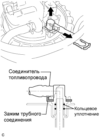
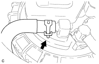
Remove the tube joint clip, then pull the fuel tube joint out of the plug of the fuel suction tube assembly.
- ПРИМЕЧАНИЕ:
- Check that there is no dirt or other foreign objects around the fuel tube joint before disconnecting it. Clean the joint if necessary.
- It is necessary to prevent mud or dirt from entering the joint. If mud or dirt gets in the joint, the O-rings may not seal properly.
- Only disconnect the joint by hand.
- Do not bend, kink or twist the nylon tubes.
- Protect the joint by covering it with a plastic bag.
| 18. REMOVE NO. 1 FUEL EVAPORATION TUBE SUB-ASSEMBLY |
Loosen the clip and remove the No. 1 fuel evaporation tube sub-assembly from the fuel suction tube assembly.
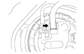
| 19. DISCONNECT FUEL TANK EVAPORATION TUBE |
Release the retainer and disconnect the No. 2 fuel tank evaporation tube from the fuel suction tube assembly.
| 20. DISCONNECT NO. 1 CHARCOAL CANISTER OUTLET HOSE |
Disconnect the No. 1 charcoal canister outlet hose from the fuel suction tube assembly.
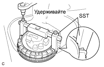
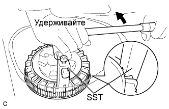
| 21. REMOVE FUEL PUMP GAUGE RETAINER |
Using a 6 mm socket hexagon wrench, set SST to the fuel pump gauge retainer.
- SST
- 09808-14020(09808-01410,09808-01420,09808-01430)
- УКАЗАНИЕ:
- Insert the notch of SST into the rib of the fuel pump gauge retainer.
Using SST, loosen the fuel pump gauge retainer.
- SST
- 09808-14020(09808-01410,09808-01420,09808-01430)
- ПРИМЕЧАНИЕ:
- Do not use any other tools such as a screwdriver.
- УКАЗАНИЕ:
- Insert the notch of SST into the rib of the fuel pump gauge retainer.
Remove the fuel pump gauge retainer while holding the fuel suction tube assembly by hand.
| 22. REMOVE FUEL SUCTION TUBE ASSEMBLY |
Remove the fuel suction tube assembly from the fuel tank.
- ПРИМЕЧАНИЕ:
- Make sure that the fuel sender gauge arm does not bend.
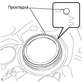
Remove the gasket from the fuel tank.
| 24. REMOVE FUEL SENDER GAUGE ASSEMBLY |
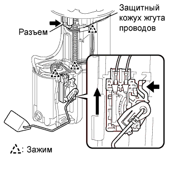
Disconnect the connector of the fuel sender gauge assembly.
Remove the harness protector from the wire harness.
Disconnect the 3 harness clamps.
- ПРИМЕЧАНИЕ:
- Do not damage the wire harness.
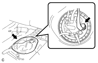
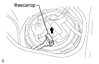
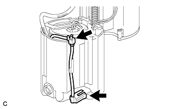
Release the lock as shown in the illustration and slide the fuel sender gauge assembly to remove it.
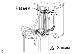
Disconnect the connector of the fuel pump harness.
Remove the 2 harness clamps.
- ПРИМЕЧАНИЕ:
- Do not damage the wire harness.
Disconnect the fuel pump filter hose.
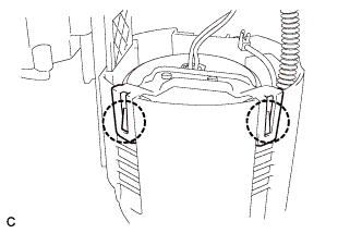
Using a screwdriver with its tip wrapped in protective tape, disengage the 2 claws, and remove the fuel filter and fuel pump from the fuel sub-tank.
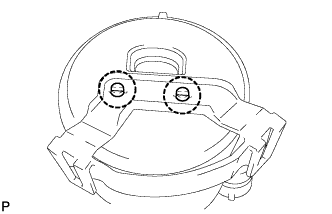
Using a screwdriver with its tip wrapped in protective tape, disengage the 2 claws and remove the No. 1 fuel suction support.
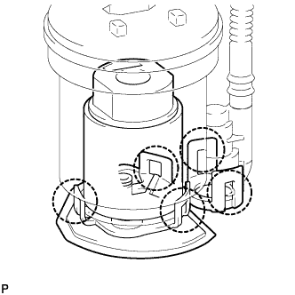
Using a screwdriver with its tip wrapped in protective tape, disengage the 5 claws, and remove the fuel pump filter and fuel pump from the fuel filter.
- ПРИМЕЧАНИЕ:
- Do not damage the fuel pump filter.
- Do not remove the suction filter.
- Do not use either the fuel pump or the suction filter if the suction filter is removed from the fuel pump.
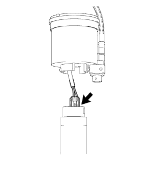
Disconnect the fuel pump harness.
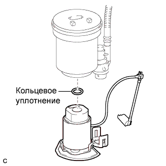
Remove the O-ring.
| 26. REMOVE FUEL PRESSURE REGULATOR ASSEMBLY |
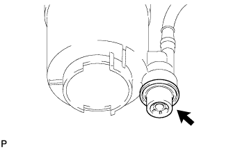
Using a screwdriver with its tip wrapped in protective tape, remove the fuel pressure regulator assembly.
- ПРИМЕЧАНИЕ:
- Slowly pull out the fuel pressure regulator assembly because the O-ring is firmly installed between the regulator and the fuel filter.
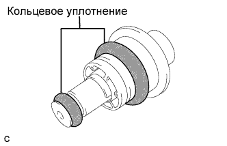
Remove the 2 O-rings from the pressure regulator assembly.