Топливный Фильтр -- Замена |
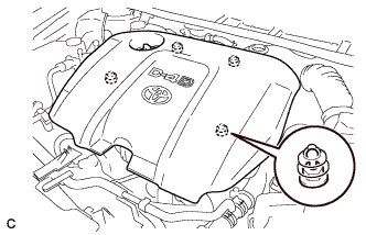
| 1. REMOVE NO. 1 ENGINE COVER |
Disengage the 4 pins and remove No. 1 engine cover sub-assembly.
 |
| 2. REMOVE AIR CLEANER CAP SUB-ASSEMBLY |
Disconnect the mass air flow meter connector.
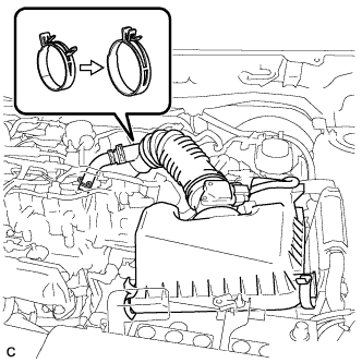 |
Disconnect the No. 2 ventilation hose.
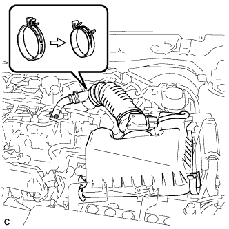
Disconnect the 2 clamps and band, and remove the air cleaner cap sub-assembly.
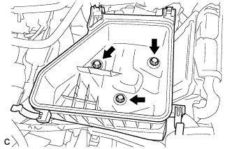
| 3. REMOVE AIR CLEANER CASE SUB-ASSEMBLY |
Remove the 3 bolts and air cleaner case sub-assembly.
 |
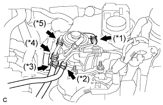
| 4. REMOVE FUEL FILTER ASSEMBLY |
Disconnect the 4 fuel hoses. (without combustion heater)
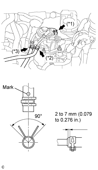
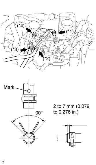
Disconnect the No. 3 fuel hose (*1).
Disconnect the No. 2 fuel hose (*2).
Disconnect the No. 1 fuel hose (*3).
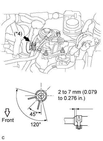
Disconnect the No. 4 fuel hose (*4).
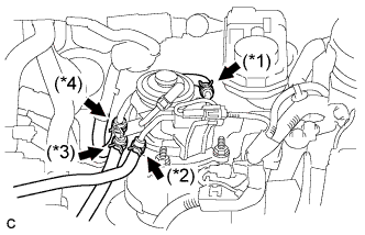
Disconnect the 5 fuel hoses. (with combustion heater)
Disconnect the No. 3 fuel hose (*1).
Disconnect the No. 2 fuel hose (*2).
Disconnect the No. 1 fuel hose (*3).
Disconnect the No. 4 fuel hose (*4).
Disconnect the heater fuel hose (*5).
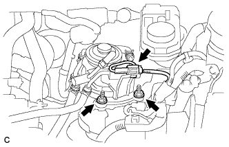
Remove the fuel filter assembly.
Disconnect the level warning switch connector.
Remove the 2 nuts and fuel filter assembly.
| 5. DRAIN FUEL |
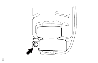
Loosen the drain bolt, and drain the fuel from the fuel filter.
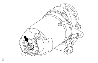 |
| 6. REMOVE FUEL FILTER GASKET |
Disconnect the level warning switch connector and harness clamp from the fuel filter cap.
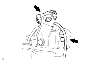 |
Remove the bolt and then remove the filter stay and filter gasket.
 |
| 7. REMOVE LEVEL WARNING SWITCH |
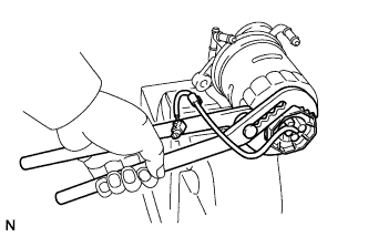
Clamp the fuel filter assembly in a vise.
- ПРИМЕЧАНИЕ:
- Be careful not to damage the fuel filter cap.
 |
Using pliers, remove the level warning switch.
- ПРИМЕЧАНИЕ:
- Be careful not to damage the level warning switch.
Remove the O-ring from the level warning switch.
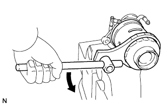
| 8. REMOVE FUEL FILTER ELEMENT |
Using SST, remove the fuel filter element.
- SST
- 09228-64030
 |
| 9. INSTALL FUEL FILTER ELEMENT |
Check and clean the installation surface of the fuel filter.
Apply fuel to the gasket of a new fuel filter element.
Lightly screw the fuel filter element into place, and tighten it until the gasket comes into contact with the seat.
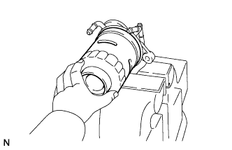 |
Tighten the fuel filter element an additional 3/4 turn by hand.
| 10. INSTALL LEVEL WARNING SWITCH |
Install a new O-ring to the level warning switch.
Apply fuel to the O-ring of the level warning switch.
Install the level warning switch to the fuel filter and tighten it by hand.
| 11. INSTALL FUEL FILTER GASKET |
Install the filter gasket and filter stay to the fuel filter assembly.
Tighten the bolt.
- Момент затяжки:
- 3.4 Н*м{35 кгс*см, 30 фунт-сила-дюймов}
|
| 12. INSTALL FUEL FILTER ASSEMBLY |
Install the fuel filter assembly.
Install the fuel filter assembly with the 2 nuts.
- Момент затяжки:
- 18 Н*м{179 кгс*см, 13 фунт-сила-футов}
Connect the level warning switch connector.
Connect the 4 fuel hoses. (without combustion heater)
Connect the No. 3 fuel hose as shown in the illustration (*1).
Connect the No. 2 fuel hose as shown in the illustration (*2).
Connect the No. 1 fuel hose as shown in the illustration (*3).
Connect the No. 4 fuel hose as shown in the illustration (*4).
Connect the 5 fuel hoses. (without combustion heater)
Connect the No. 3 fuel hose as shown in the illustration (*1).
Connect the No. 2 fuel hose as shown in the illustration (*2).
Connect the No. 1 fuel hose as shown in the illustration (*3).
Connect the heater fuel hose as shown in the illustration (*4).
Connect the No. 4 fuel hose as shown in the illustration (*5).

| 13. INSTALL AIR CLEANER CASE SUB-ASSEMBLY |
Install the air cleaner case sub-assembly with the 3 bolts.
- Момент затяжки:
- 7.0 Н*м{71 кгс*см, 62 фунт-сила-дюймов}
|
| 14. INSTALL AIR CLEANER CAP SUB-ASSEMBLY |
Install the air cleaner cap sub-assembly, and connect the 2 clamps and band.
 |
Connect the No. 2 ventilation hose.
Connect the mass air flow meter connector.
| 15. INSPECT FOR FUEL LEAK |
- УКАЗАНИЕ:
- Using the intelligent tester to perform Active Tests allow relays, VSVs, actuators and other items to be operated without removing any parts. This non-intrusive functional inspection can be very useful because intermittent operation may be discovered before parts or wiring is disturbed. Performing Active Tests early in troubleshooting is one way to save diagnostic time. Data List information can be displayed while performing Active Tests.
- The Data List can be displayed during Active Tests.
Connect an intelligent tester to the DLC3.
Turn the ignition switch to the ON position.
Turn the tester on.
Enter the following menu items: Powertrain / Engine and ECT / Active Test.
Perform the Active Test.
Tester Display Test Part Control Range Diagnostic Notes Active the fuel leak test Pressurize common rail internal fuel pressure, in order to see if fuel leaks ON/OFF - Fuel pressure inside common rail pressurized to 135 MPa and engine speed increased to 2000 rpm when ON selected
- Above conditions preserved while test ON
- Fuel pressure inside common rail pressurized to 135 MPa and engine speed increased to 2000 rpm when ON selected
| 16. INSTALL NO. 1 ENGINE COVER |
Fit the 4 retainers and install the No. 1 engine cover.