Топливный Фильтр -- Замена |
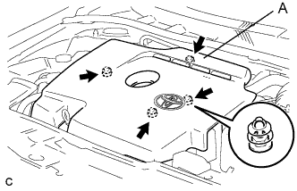
| 1. REMOVE NO. 1 ENGINE COVER |
Detach the 4 clips and remove the engine cover.
- ПРИМЕЧАНИЕ:
- Lift the area around the clips on the top of the engine cover.
- Do not suddenly lift the engine cover. Remove the cover slowly by detaching the clips on by one.
- Lift area A shown in the illustration particularly slowly because there is a cowl on the top of the area around A. Failure to do so may damage the cover.
 |
| 2. REMOVE AIR CLEANER CAP SUB-ASSEMBLY |
Disconnect the mass air flow meter connector.
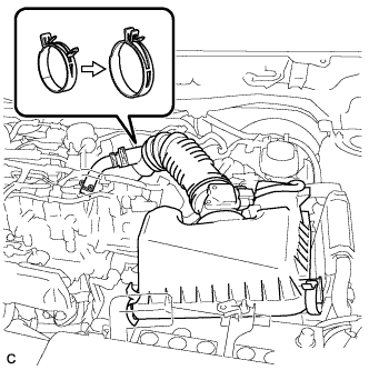 |
Disconnect the No. 2 ventilation hose.
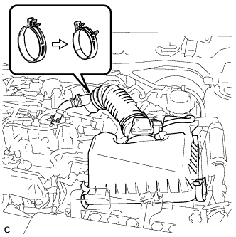
Disconnect the 2 clamps and band, and remove the air cleaner cap sub-assembly.
Remove the air cleaner filter element.
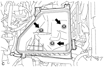
| 3. REMOVE AIR CLEANER CASE SUB-ASSEMBLY |
Remove the 3 bolts and air cleaner case.
 |
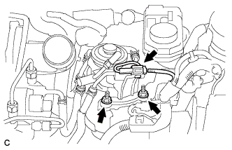
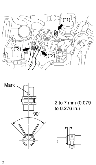
| 4. REMOVE FUEL FILTER ASSEMBLY |
Disconnect the 4 fuel hoses. (w/o combustion type power heater)
Disconnect the No. 3 fuel hose (*1).
Disconnect the No. 2 fuel hose (*2).
Disconnect the No. 1 fuel hose (*3).
Disconnect the No. 4 fuel hose (*4).
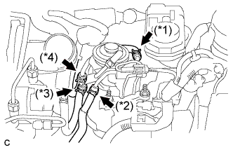
Disconnect the 5 fuel hoses. (w/ combustion type power heater)
Disconnect the No. 3 fuel hose (*1).
Disconnect the No. 2 fuel hose (*2).
Disconnect the No. 1 fuel hose (*3).
Disconnect the No. 4 fuel hose (*4).
Disconnect the heater fuel hose (*5).

Remove the fuel filter assembly.
Disconnect the level warning switch connector.
Remove the 2 nuts and fuel filter assembly.
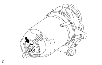
| 5. DRAIN FUEL |
Loosen the drain bolt, and drain the fuel from the fuel filter.
 |
| 6. REMOVE FUEL FILTER GASKET |
Disconnect the level warning switch connector and harness clamp from the fuel filter cap.
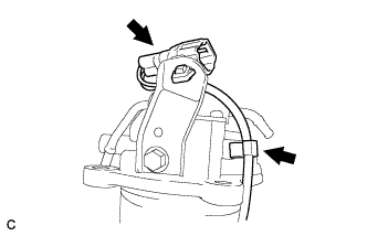 |
Remove the bolt and then remove the filter stay and filter gasket.
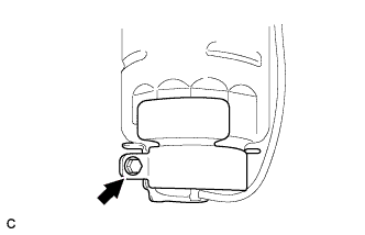 |
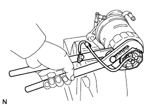
| 7. REMOVE LEVEL WARNING SWITCH |
Clamp the fuel filter assembly in a vise.
- ПРИМЕЧАНИЕ:
- Be careful not to damage the fuel filter cap.
 |
Using pliers, remove the level warning switch.
- ПРИМЕЧАНИЕ:
- Be careful not to damage the level warning switch.
Remove the O-ring from the level warning switch.
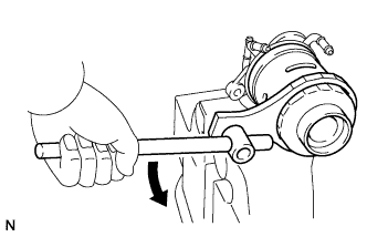
| 8. REMOVE FUEL FILTER ELEMENT |
Using SST, remove the fuel filter element.
- SST
- 09228-64030
 |
| 9. INSTALL FUEL FILTER ELEMENT |
Check and clean the installation surface of the fuel filter.
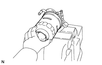 |
Apply fuel to the gasket of a new fuel filter element.
Lightly screw the fuel filter element into place, and tighten it until the gasket comes into contact with the seat.
Tighten the fuel filter element an additional 3/4 turn by hand.
| 10. INSTALL LEVEL WARNING SWITCH |
Install a new O-ring to the level warning switch.
Apply fuel to the O-ring of the level warning switch.
Install the level warning switch to the fuel filter and tighten it by hand.
| 11. INSTALL FUEL FILTER GASKET |
Install the filter gasket and filter stay to the fuel filter assembly.
Tighten the bolt.
- Момент затяжки:
- 3.4 Н*м{35 кгс*см, 30 фунт-сила-дюймов}
|
| 12. INSTALL FUEL FILTER ASSEMBLY |
Install the fuel filter assembly.
Install the fuel filter assembly with the 2 nuts.
- Момент затяжки:
- 17 Н*м{173 кгс*см, 13 фунт-сила-футов}
Connect the level warning switch connector.
Connect the 4 fuel hoses. (w/o combustion type power heater)
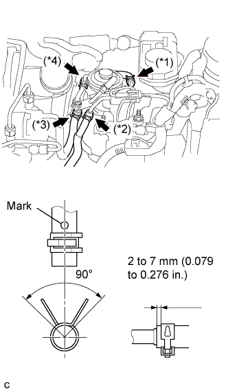
Connect the No. 3 fuel hose as shown in the illustration (*1).
Connect the No. 2 fuel hose as shown in the illustration (*2).
Connect the No. 1 fuel hose as shown in the illustration (*3).
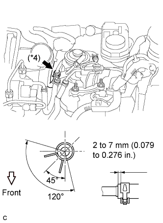
Connect the No. 4 fuel hose as shown in the illustration (*4).
Connect the 5 fuel hoses. (w/ combustion type power heater)
Connect the No. 3 fuel hose as shown in the illustration (*1).
Connect the No. 2 fuel hose as shown in the illustration (*2).
Connect the No. 1 fuel hose as shown in the illustration (*3).
Connect the heater fuel hose as shown in the illustration (*4).
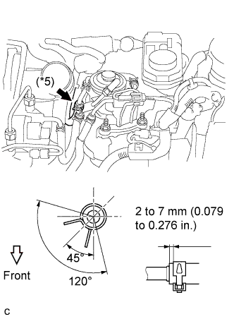
Connect the No. 4 fuel hose as shown in the illustration (*5).
| 13. INSTALL AIR CLEANER CASE SUB-ASSEMBLY |
Install the 3 bolts and air cleaner case.
- Момент затяжки:
- 7.0 Н*м{71 кгс*см, 62 фунт-сила-дюймов}
|
| 14. INSTALL AIR CLEANER CAP SUB-ASSEMBLY |
Install the air cleaner filter element.
Install the air cleaner cap sub-assembly, and connect the 2 clamps and band.
 |
Connect the No. 2 ventilation hose.
Connect the mass air flow meter connector.
| 15. INSPECT FOR FUEL LEAK |
PERFORM ACTIVE TEST
Connect the intelligent tester to the DLC3.
Turn the ignition switch to the ON position.
Turn the intelligent tester on.
Enter the following menus: Powertrain / Engine / Active Test.
Perform the Active Test.
Tester Display Test Part Control Range Diagnostic Notes Test the Fuel Leak Pressurizing common rail internal fuel pressure, and checking for fuel leaks. Stop/Start - Fuel pressure inside common rail is pressurized to specified value and engine speed is increased to 2000 rpm when ON is selected.
- Above conditions are maintained while test is ON.
- Fuel pressure inside common rail is pressurized to specified value and engine speed is increased to 2000 rpm when ON is selected.
| 16. INSTALL NO. 1 ENGINE COVER |
Attach the 4 clips to install the engine cover.
- ПРИМЕЧАНИЕ:
- Line up the 4 grommets using the oil filler cap and oil dipstick as guides.
- Push down on the four locations shown to install the cover.
 |