READ VALUE OF INTELLIGENT TESTER (VEHICLE SPEED)
CHECK COMBINATION METER SYSTEM
CHECK HARNESS AND CONNECTOR (ECM - COMBINATION METER)
CHECK HARNESS AND CONNECTOR (ECM NO. 4 JUNCTION BLOCK)
DTC P0500 Vehicle Speed Sensor "A" |
DESCRIPTION
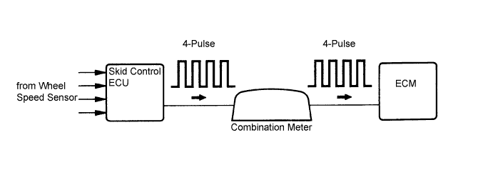
The wheel speed sensor monitors the wheel rotation speed and sends a signal to the skid control ECU. The skid control ECU converts the wheel speed signal into a 4-pulse signal and transmits it to the ECM via the combination meter. The ECM determines the vehicle speed based on the frequency of the pulse signal.- УКАЗАНИЕ:
- A voltage of 12 V or 5 V is output from each ECU and then input to the combination meter. The signal is changed to pulse signal at the transistor in the combination meter. Each ECU controls the respective system based on the pulse signal.
- If a short occurs in any of the ECUs or in the wire harness connected to an ECU, all systems in the diagram below will not operate normally.
| DTC No. | DTC Detection Condition | Trouble Area |
| P0500 | While vehicle being driven, no vehicle speed sensor signal to ECM. (2 trip detection logic) |
|
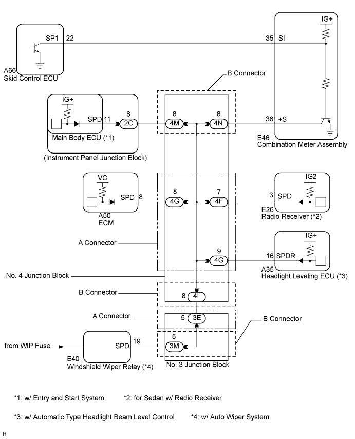
WIRING DIAGRAM
INSPECTION PROCEDURE
- УКАЗАНИЕ:
- Read freeze frame data using the intelligent tester. The ECM records vehicle and driving condition information as freeze frame data the moment a DTC is stored. When troubleshooting, freeze frame data can help determine if the vehicle was moving or stationary, if the engine was warmed up or not, if the air fuel ratio was lean or rich, and other data from the time the malfunction occurred.
| 1.READ VALUE OF INTELLIGENT TESTER (VEHICLE SPEED) |
Connect the intelligent tester to the DLC3.
Turn the ignition switch on (IG).
Turn the tester on.
Select the following menu items: Powertrain / Engine and ECT / Data List / Vehicle Speed.
Drive the vehicle.
Read the value displayed on the tester.
- OK:
- Vehicle speeds displayed on tester and speedometer display are equal.
|
| ||||
| OK | ||
| ||
| 2.CHECK COMBINATION METER SYSTEM |
The circuits that send vehicle speed signals to this system are inspected in the meter system (See page Нажмите здесь).
During inspection for the meter section, if there is an instruction that indicates to go back inspections for each system, proceed to the next step.
| NEXT | |
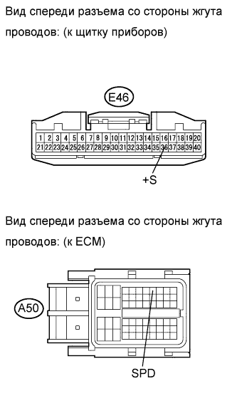
| 3.CHECK HARNESS AND CONNECTOR (ECM - COMBINATION METER) |
Disconnect the ECM connector.
 |
Disconnect the combination meter connector.
Measure the resistance according to the value(s) in the table below.
- Standard resistance (Check for open):
Tester Connection Condition Specified Condition E46-36 (+S) - A50-8 (SPD) Always Below 1 Ω
Reconnect the ECM connector.
Reconnect the combination meter connector.
|
| ||||
| OK | ||
| ||
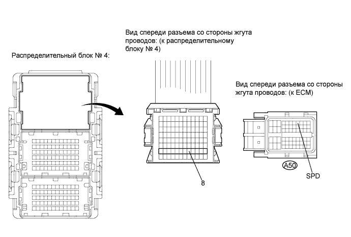
| 4.CHECK HARNESS AND CONNECTOR (ECM NO. 4 JUNCTION BLOCK) |
Disconnect the ECM connector.
Disconnect the No. 4 junction block connector.
Measure the resistance according to the value(s) in the table below.
- Standard resistance (Check for open):
Tester Connection Condition Specified Condition 4G-8 - A50-8 (SPD) Always Below 1 Ω
Reconnect the ECM connector.
Reconnect the No. 4 junction block connector.
|
| ||||
| OK | ||
| ||