Система Ecd Сигнальная Цепь Стартера. Corolla Auris
Двигатель. COROLLA, AURIS. ZZE150 ZRE151,152 NDE150
DESCRIPTION
WIRING DIAGRAM
INSPECTION PROCEDURE
READ VALUE OF INTELLIGENT TESTER (STARTER SIGNAL)
CHECK ST RELAY (POWER SOURCE)
INSPECT ST RELAY
CHECK HARNESS AND CONNECTOR (ST RELAY - BODY GROUND)
CHECK HARNESS AND CONNECTOR (ST RELAY - CLUTCH PEDAL SWITCH)
INSPECT CLUTCH PEDAL SWITCH
CHECK HARNESS AND CONNECTOR (CLUTCH PEDAL SWITCH - IGNITION SWITCH)
INSPECT IGNITION SWITCH
INSPECT FUSE (AM1 FUSE)
СИСТЕМА ECD - Сигнальная цепь стартера |
DESCRIPTION
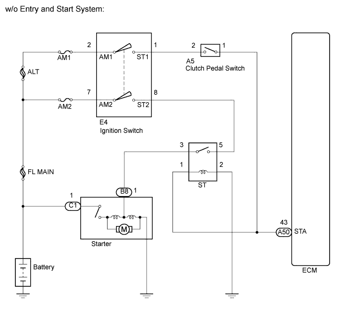
While the engine is being cranked, current flows from terminal ST1 of the ignition switch to the clutch pedal switch and also flows to terminal STA of the ECM (STA signal).
WIRING DIAGRAM
INSPECTION PROCEDURE
- УКАЗАНИЕ:
- This chart is based on the premise that the engine can crank normally. If the engine cannot crank normally, proceed to PROBLEM SYMPTOMS TABLE (See page Нажмите здесь).
| 1.READ VALUE OF INTELLIGENT TESTER (STARTER SIGNAL) |
Connect the intelligent tester to the DLC3.
Turn the ignition switch on (IG).
Turn the tester on.
Enter the following menu items: Powertrain / Engine and ECT / Data List / Starter Signal.
Read the value.
- OK:
Ignition Switch
| Starter Signal
|
On (IG)
| OFF
|
START
| ON
|
| OK |
|
|
|
| PROCEED TO NEXT CIRCUIT INSPECTION SHOWN IN PROBLEM SYMPTOMS TABLE (Нажмите здесь) |
|
| 2.CHECK ST RELAY (POWER SOURCE) |
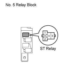
Remove the ST relay from the No. 5 relay block.
Measure the voltage according to the value(s) in the table below.
- Standard voltage:
Tester Connection
| Condition
| Specified Condition
|
1 (ST relay) - Body ground
| Engine cranking
| 11 to 14 V
|
Reinstall the ST relay.
Remove the ST relay from the No. 5 relay block.
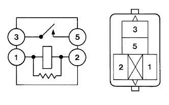
Measure the resistance according to the value(s) in the table below.
- Standard resistance:
Tester Connection
| Condition
| Specified Condition
|
3 - 5
| Battery voltage is not applied between terminals 1 and 2
| 10 kΩ or higher
|
3 - 5
| Battery voltage is applied between terminals 1 and 2
| Below 1 Ω
|
Reinstall the ST relay.
| 4.CHECK HARNESS AND CONNECTOR (ST RELAY - BODY GROUND) |
Remove the ST relay from the No. 5 relay block.
Measure the resistance according to the value(s) in the table below.
- Standard resistance:
Tester Connection
| Condition
| Specified Condition
|
2 (ST relay) - Body ground
| Always
| Below 1 Ω
|
Reconnect the ST relay.
| | REPAIR OR REPLACE HARNESS OR CONNECTOR (ST RELAY - BODY GROUND) |
|
|
| OK |
|
|
|
| REPAIR OR REPLACE HARNESS OR CONNECTOR (ECM - CLUTCH PEDAL SWITCH) |
|
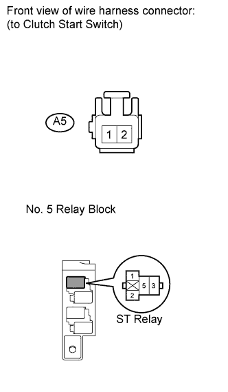
| 5.CHECK HARNESS AND CONNECTOR (ST RELAY - CLUTCH PEDAL SWITCH) |
Remove the ST relay from the No. 5 relay block.
Disconnect the clutch pedal switch connector.
Disconnect the ECM connector.
Measure the resistance according to the value(s) in the table below.
- Standard resistance (check for open):
Tester Connection
| Condition
| Specified Condition
|
1 (ST relay) - A5-1
| Always
| Below 1 Ω
|
- Standard resistance (check for short):
Tester Connection
| Condition
| Specified Condition
|
1 (ST relay) or A5-1 Body ground
| Always
| 10 kΩ or higher
|
Reinstall the ST relay.
Reconnect the clutch pedal switch connector.
Reconnect the ECM connector.
| | REPAIR OR REPLACE HARNESS OR CONNECTOR (ST RELAY - CLUTCH PEDAL SWITCH) |
|
|
| 6.INSPECT CLUTCH PEDAL SWITCH |
Inspect the clutch pedal switch (See page Нажмите здесь).
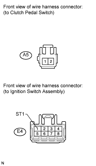
| 7.CHECK HARNESS AND CONNECTOR (CLUTCH PEDAL SWITCH - IGNITION SWITCH) |
Disconnect the clutch pedal switch connector.
Disconnect the ignition switch connector.
Measure the resistance according to the value(s) in the table below.
- Standard resistance (check for open):
Tester Connection
| Condition
| Specified Condition
|
A5-2 - E4-1 (ST1)
| Always
| Below 1 Ω
|
- Standard resistance (check for short):
Tester Connection
| Condition
| Specified Condition
|
A5-2 or E4-1 (ST1) - Body ground
| Always
| 10 kΩ or higher
|
Reconnect the clutch pedal switch connector.
Reconnect the ignition switch connector.
| | REPAIR OR REPLACE HARNESS OR CONNECTOR (CLUTCH PEDAL SWITCH - IGNITION SWITCH) |
|
|
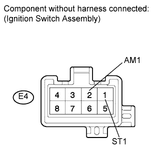
| 8.INSPECT IGNITION SWITCH |
Disconnect the ignition switch connector.
Measure the resistance according to the value(s) in the table below.
- Standard resistance:
Tester Connection
| Ignition Switch Position
| Specified Condition
|
All terminals
| LOCK
| 10 kΩ or higher
|
E4-2 (AM1) - E4-1 (ST1)
| START
| Below 1 Ω
|
Reconnect the ignition switch connector.
| 9.INSPECT FUSE (AM1 FUSE) |
Remove the AM1 fuse from the instrument panel junction block.
Measure the resistance according to the value(s) in the table below.
- Standard resistance:
Tester Connection
| Condition
| Specified Condition
|
AM1 fuse
| Always
| Below 1 Ω
|
Reinstall the AM1 fuse.
| OK |
|
|
|
| REPAIR OR REPLACE HARNESS OR CONNECTOR (IGNITION SWITCH - BATTERY) |
|