Двигатель. COROLLA, AURIS. ZZE150 ZRE151,152 NDE150
DESCRIPTION
WIRING DIAGRAM
INSPECTION PROCEDURE
READ VALUE OF INTELLIGENT TESTER (STARTER SIGNAL)
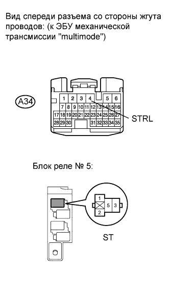
CHECK ST RELAY (POWER SOURCE)
INSPECT ST RELAY
CHECK HARNESS AND CONNECTOR (ST RELAY - BODY GROUND)
CHECK HARNESS AND CONNECTOR (ST RELAY - CLUTCH PEDAL SWITCH)
INSPECT CLUTCH PEDAL SWITCH ASSEMBLY
CHECK HARNESS AND CONNECTOR (CLUTCH PEDAL SWITCH - IGNITION SWITCH)
INSPECT IGNITION SWITCH ASSEMBLY
INSPECT FUSE (AM1 FUSE)
CHECK HARNESS AND CONNECTOR (ST RELAY - TCM)
CHECK TCM (TMN VOLTAGE)
CHECK HARNESS AND CONNECTOR (TCM - PARK/NEUTRAL POSITION SWITCH)
INSPECT PARK/NEUTRAL POSITION SWITCH ASSEMBLY
CHECK HARNESS AND CONNECTOR (PARK/NEUTRAL POSITION SWITCH - IGNITION SWITCH)
INSPECT IGNITION SWITCH ASSEMBLY
INSPECT FUSE (AM1 FUSE)
СИСТЕМА ECD - Сигнальная цепь стартера |
DESCRIPTION
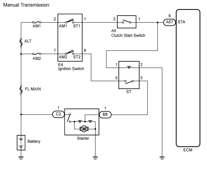
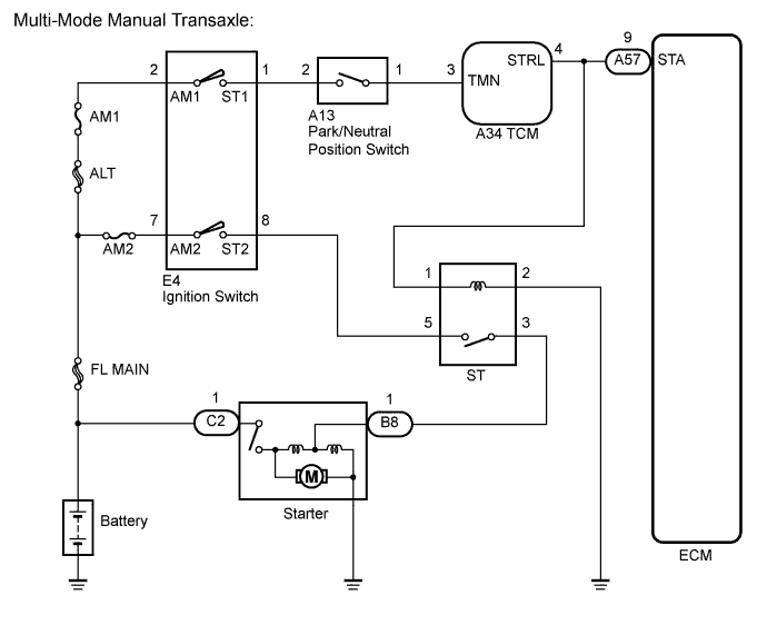
While the engine is being cranked, current flows from terminal ST1 of the ignition switch to the park/neutral position switch (for multi-mode manual transaxle) or clutch pedal switch (for manual transaxle) and also flows to terminal STA of the ECM (STA Signal).
WIRING DIAGRAM
INSPECTION PROCEDURE
- УКАЗАНИЕ:
- This chart is based on the premise that the engine can crank normally. If the engine cannot crank normally, proceed to PROBLEM SYMPTOMS TABLE (See page Нажмите здесь).
| 1.READ VALUE OF INTELLIGENT TESTER (STARTER SIGNAL) |
Connect the intelligent tester to the DLC3.
Turn the ignition switch to the ON position.
Turn the tester on.
Enter the following menu items: Powertrain / Engine and ECT / Data List / Starter SIG.
Read the values.
- OK:
Ignition Switch Position
| Starter Signal
|
ON
| OFF
|
START
| ON
|
| OK |
|
|
|
| PROCEED TO NEXT CIRCUIT INSPECTION SHOWN IN PROBLEM SYMPTOMS TABLE |
|
| 2.CHECK ST RELAY (POWER SOURCE) |
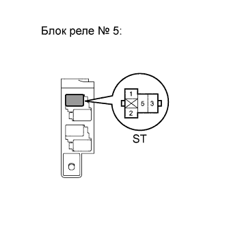
Remove the ST relay from the No. 5 relay block.
Measure the voltage according to the value(s) in the table below.
- Standard voltage:
Tester Connection
| Condition
| Specified Condition
|
ST relay terminal 1 - Body ground
| Engine cranking
| 9 to 14 V
|
Reinstall the ST relay.
- Result:
Result
| Proceed to
|
OK
| A
|
NG (Manual transmission)
| B
|
NG (Multi-mode manual transmission)
| C
|
Remove the ST relay from the No. 5 relay block.
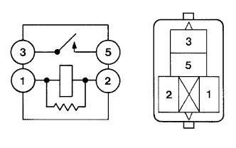
Measure the resistance according to the value(s) in the table below.
- Standard resistance:
Tester Connection
| Condition
| Specified Condition
|
3 - 5
| Normal
| 10 kΩ or higher
|
3 - 5
| Battery voltage applied between terminals 1 and 2
| Below 1 Ω
|
Reinstall the ST relay.
| 4.CHECK HARNESS AND CONNECTOR (ST RELAY - BODY GROUND) |
Remove the ST relay from the No. 5 relay block.
Measure the resistance according to the value(s) in the table below.
- Standard resistance:
Tester Connection
| Condition
| Specified Condition
|
ST relay terminal 2 - Body ground
| Always
| Below 1 Ω
|
Reconnect the ST relay.
- Result:
Result
| Proceed to
|
OK (Manual transmission)
| A
|
OK (Multi-mode manual transmission)
| B
|
NG
| C
|
| | REPAIR OR REPLACE HARNESS OR CONNECTOR (ECM - TCM) |
|
|
| | REPAIR OR REPLACE HARNESS OR CONNECTOR (ST RELAY - BODY GROUND) |
|
|
| A |
|
|
|
| REPAIR OR REPLACE HARNESS OR CONNECTOR (ECM - CLUTCH PEDAL SWITCH) |
|
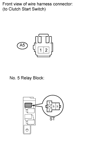
| 5.CHECK HARNESS AND CONNECTOR (ST RELAY - CLUTCH PEDAL SWITCH) |
Remove the ST relay from the No. 5 relay block.
Disconnect the clutch pedal switch connector.
Measure the resistance according to the value(s) in the table below.
- Standard resistance (check for open):
Tester Connection
| Condition
| Specified Condition
|
ST relay terminal 1 - A5-1
| Always
| Below 1 Ω
|
- Standard resistance (check for short):
Tester Connection
| Condition
| Specified Condition
|
ST relay terminal 1 or A5-1 Body ground
| Always
| 10 kΩ or higher
|
Reinstall the ST relay.
Reconnect the clutch pedal switch connector.
| | REPAIR OR REPLACE HARNESS OR CONNECTOR (ST RELAY - CLUTCH PEDAL SWITCH) |
|
|
| 6.INSPECT CLUTCH PEDAL SWITCH ASSEMBLY |
Inspect the clutch pedal switch assembly (See page Нажмите здесь).
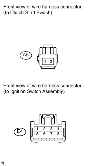
| 7.CHECK HARNESS AND CONNECTOR (CLUTCH PEDAL SWITCH - IGNITION SWITCH) |
Disconnect the clutch pedal switch connector.
Disconnect the ignition switch connector.
Measure the resistance according to the value(s) in the table below.
- Standard resistance (check for open):
Tester Connection
| Condition
| Specified Condition
|
A5-2 - E4-1 (ST1)
| Always
| Below 1 Ω
|
- Standard resistance (check for short):
Tester Connection
| Condition
| Specified Condition
|
A5-2 or E4-1 (ST1) - Body ground
| Always
| 10 kΩ or higher
|
Reconnect the clutch pedal switch connector.
Reconnect the ignition switch connector.
| | REPAIR OR REPLACE HARNESS OR CONNECTOR (CLUTCH PEDAL SWITCH - IGNITION SWITCH) |
|
|
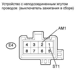
| 8.INSPECT IGNITION SWITCH ASSEMBLY |
Disconnect the ignition switch connector.
Measure the resistance according to the value(s) in the table below.
- Standard resistance:
Tester Connection
| Ignition Switch Position
| Specified Condition
|
All terminals
| LOCK
| 10 kΩ or higher
|
E4-2 (AM1) - E4-1 (ST1)
| START
| Below 1 Ω
|
Reconnect the ignition switch connector.
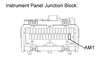
| 9.INSPECT FUSE (AM1 FUSE) |
Remove the AM1 fuse from the instrument panel junction block.
Measure the resistance according to the value(s) in the table below.
- Standard resistance:
Tester Connection
| Condition
| Specified Condition
|
AM1 fuse
| Always
| Below 1 Ω
|
Reinstall the AM1 fuse.
| OK |
|
|
|
| REPAIR OR REPLACE HARNESS OR CONNECTOR (IGNITION SWITCH - BATTERY) |
|
| 10.CHECK HARNESS AND CONNECTOR (ST RELAY - TCM) |
Remove the ST relay from the No. 5 relay block.
Disconnect the TCM connector.
Measure the resistance according to the value(s) in the table below.
- Standard resistance (check for open):
Tester Connection
| Condition
| Specified Condition
|
ST relay terminal 1 - A34-4 (STRL)
| Always
| Below 1 Ω
|
- Standard resistance (check for short):
Tester Connection
| Condition
| Specified Condition
|
ST relay terminal 1 or A34-4 (STRL) - Body ground
| Always
| 10 kΩ or higher
|
Reinstall the ST relay.
Reconnect the TCM connector.
| | REPAIR OR REPLACE HARNESS OR CONNECTOR (ST RELAY - TCM) |
|
|
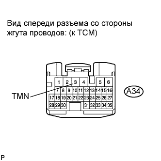
| 11.CHECK TCM (TMN VOLTAGE) |
Disconnect the TCM connector.
Measure the voltage according to the value(s) in the table below.
- Standard voltage:
Tester Connection
| Condition
| Specified Condition
|
A34-3 (TMN) - Body ground
| Engine cranking
| 11 to 14 V
|
Reconnect the TCM connector.
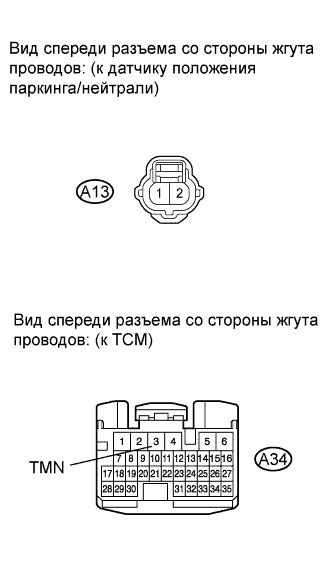
| 12.CHECK HARNESS AND CONNECTOR (TCM - PARK/NEUTRAL POSITION SWITCH) |
Disconnect the TCM connector.
Disconnect the park/neutral position switch connector.
Measure the resistance according to the value(s) in the table below.
- Standard resistance (check for open):
Tester Connection
| Condition
| Specified Condition
|
A34-3 (TMN) - A13-1
| Always
| Below 1 Ω
|
- Standard resistance (check for short):
Tester Connection
| Condition
| Specified Condition
|
A34-3 (TMN) or A13-1 - Body ground
| Always
| 10 kΩ or higher
|
Reconnect the TCM connector.
Reconnect the park/neutral position switch connector.
| | REPAIR OR REPLACE HARNESS AND CONNECTOR (TCM - PARK/NEUTRAL POSITION SWITCH) |
|
|
| 13.INSPECT PARK/NEUTRAL POSITION SWITCH ASSEMBLY |
Inspect the park/neutral position switch assembly (See page Нажмите здесь).
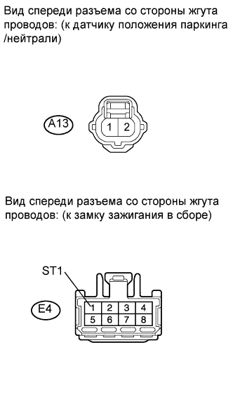
| 14.CHECK HARNESS AND CONNECTOR (PARK/NEUTRAL POSITION SWITCH - IGNITION SWITCH) |
Disconnect the park/neutral position switch connector.
Disconnect the ignition switch connector.
Measure the resistance according to the value(s) in the table below.
- Standard resistance (check for open):
Tester Connection
| Condition
| Specified Condition
|
A13-2 - E4-1 (ST1)
| Always
| Below 1 Ω
|
- Standard resistance (check for short):
Tester Connection
| Condition
| Specified Condition
|
A13-2 or E4-1 (ST1) - Body ground
| Always
| 10 kΩ or higher
|
Reconnect the park/neutral position switch connector.
Reconnect the ignition switch connector.
| | REPAIR OR REPLACE HARNESS OR CONNECTOR (PARK/NEUTRAL POSITION SWITCH - IGNITION SWITCH) |
|
|
| 15.INSPECT IGNITION SWITCH ASSEMBLY |
Disconnect the ignition switch assembly connector.
Measure the resistance according to the value(s) in the table below.
- Standard resistance:
Tester Connection
| Ignition Switch Position
| Specified Condition
|
All terminals
| LOCK
| 10 kΩ or higher
|
E4-2 (AM1) - E4-1 (ST1)
| START
| Below 1 Ω
|
Reconnect the ignition switch assembly connector.
| 16.INSPECT FUSE (AM1 FUSE) |
Remove the AM1 fuse from the instrument panel junction block.
Measure the resistance according to the value(s) in the table below.
- Standard resistance:
Tester Connection
| Condition
| Specified Condition
|
AM1 fuse
| Always
| Below 1 Ω
|
Reinstall the AM1 fuse.
| OK |
|
|
|
| REPAIR OR REPLACE HARNESS OR CONNECTOR (IGNITION SWITCH ASSEMBLY - BATTERY) |
|