Блок Двигателя Разборка. Corolla Auris
Двигатель. COROLLA, AURIS. ZZE150 ZRE151,152 NDE150
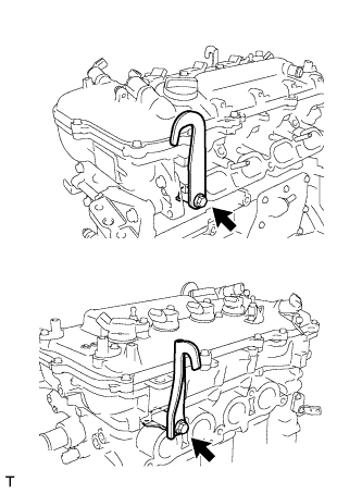
REMOVE ENGINE HANGER
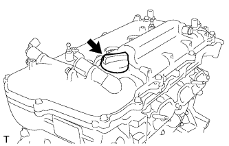
REMOVE OIL FILLER CAP SUB-ASSEMBLY
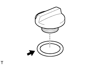
REMOVE OIL FILLER CAP GASKET
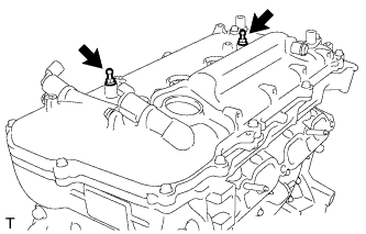
REMOVE ENGINE COVER JOINT
REMOVE SPARK PLUG
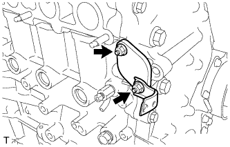
REMOVE CAMSHAFT POSITION SENSOR
REMOVE CAMSHAFT TIMING OIL CONTROL VALVE ASSEMBLY
REMOVE CYLINDER HEAD COVER SUB-ASSEMBLY
REMOVE CYLINDER HEAD COVER GASKET
SET NO. 1 CYLINDER TO TDC/COMPRESSION
REMOVE CRANKSHAFT PULLEY
REMOVE NO. 1 CHAIN TENSIONER ASSEMBLY
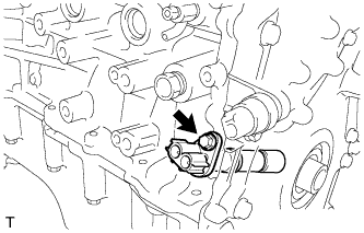
REMOVE CRANKSHAFT POSITION SENSOR
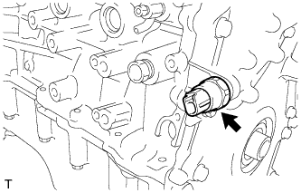
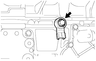
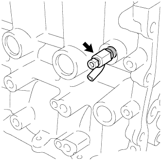
REMOVE ENGINE OIL PRESSURE SWITCH ASSEMBLY
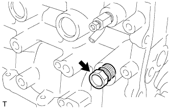
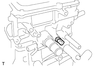
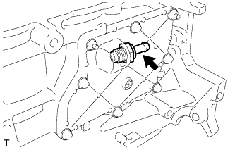
REMOVE NO. 1 TAPER SCREW PLUG
REMOVE KNOCK CONTROL SENSOR
REMOVE ENGINE COOLANT TEMPERATURE SENSOR
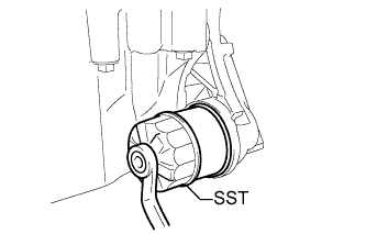
REMOVE OIL FILTER SUB-ASSEMBLY
REMOVE TIMING CHAIN COVER SUB-ASSEMBLY
REMOVE TIMING CHAIN COVER OIL SEAL
REMOVE WATER INLET HOUSING
REMOVE NO. 1 GENERATOR BRACKET
REMOVE CHAIN TENSIONER SLIPPER
REMOVE NO. 1 CHAIN VIBRATION DAMPER
REMOVE CHAIN SUB-ASSEMBLY
REMOVE NO. 2 CHAIN VIBRATION DAMPER
REMOVE CRANKSHAFT TIMING SPROCKET
REMOVE NO. 2 CHAIN SUB-ASSEMBLY
REMOVE NO. 1 CRANKSHAFT POSITION SENSOR PLATE
REMOVE CRANKSHAFT TIMING GEAR KEY
REMOVE CAMSHAFT TIMING EXHAUST GEAR ASSEMBLY
REMOVE CAMSHAFT BEARING CAP
REMOVE NO. 1 VALVE ROCKER ARM SUB-ASSEMBLY
REMOVE VALVE LASH ADJUSTER ASSEMBLY
REMOVE CAMSHAFT TIMING GEAR ASSEMBLY
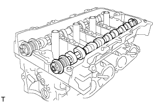
REMOVE CAMSHAFT
REMOVE NO. 2 CAMSHAFT
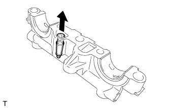
REMOVE OIL CONTROL VALVE FILTER
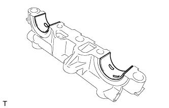
REMOVE NO. 1 CAMSHAFT BEARING
REMOVE NO. 2 CAMSHAFT BEARING
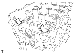
REMOVE CAMSHAFT HOUSING SUB-ASSEMBLY
REMOVE CYLINDER HEAD SUB-ASSEMBLY
REMOVE CYLINDER HEAD GASKET
REMOVE CYLINDER BLOCK WATER DRAIN COCK SUB-ASSEMBLY
REMOVE VENTILATION VALVE SUB-ASSEMBLY
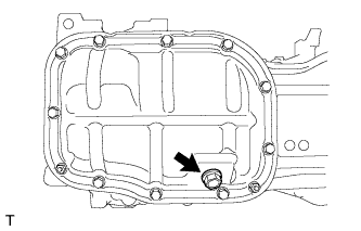
REMOVE OIL PAN DRAIN PLUG
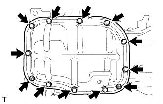
REMOVE NO. 2 OIL PAN SUB-ASSEMBLY
REMOVE OIL PUMP ASSEMBLY
REMOVE ENGINE REAR OIL SEAL
REMOVE STIFFENING CRANKCASE ASSEMBLY
Блок Двигателя -- Разборка |
Remove the 2 bolts and 2 engine hangers.
| 2. REMOVE OIL FILLER CAP SUB-ASSEMBLY |
Remove the oil filler cap.
| 3. REMOVE OIL FILLER CAP GASKET |
Remove the oil filler cap gasket.
| 4. REMOVE ENGINE COVER JOINT |
Remove the 2 engine cover joints.
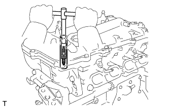
Using a 14 mm spark plug wrench, remove the spark plugs.
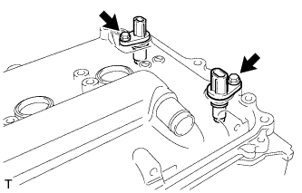
| 6. REMOVE CAMSHAFT POSITION SENSOR |
Remove the 2 bolts and 2 sensors.
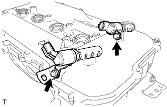
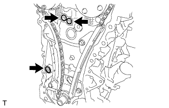
| 7. REMOVE CAMSHAFT TIMING OIL CONTROL VALVE ASSEMBLY |
Remove the 2 bolts, O-rings, bracket and 2 oil control valves.
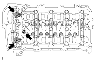
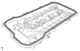
| 8. REMOVE CYLINDER HEAD COVER SUB-ASSEMBLY |
Remove the 13 bolts, seal washer and cylinder head cover.
Remove the 3 gaskets from the camshaft bearing cap.
- ПРИМЕЧАНИЕ:
- Be careful not to drop any of the gaskets into the engine when removing the cylinder head cover because gaskets may stick to the cylinder head cover.
| 9. REMOVE CYLINDER HEAD COVER GASKET |
Remove the cylinder head cover gasket.
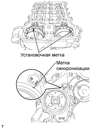
| 10. SET NO. 1 CYLINDER TO TDC/COMPRESSION |
Turn the crankshaft pulley until its groove and the timing mark "0" of the timing chain cover are aligned.
Check that each timing mark of the camshaft timing gear and sprocket are aligned with each timing mark located on the No. 1 and No. 2 bearing caps as shown in the illustration. If not, turn the crankshaft by 1 revolution (360°) to align the timing marks as above.
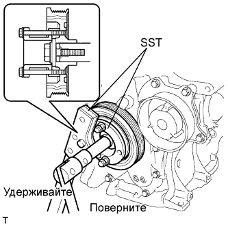
| 11. REMOVE CRANKSHAFT PULLEY |
Using SST, hold the pulley in place and loosen the pulley bolt.
- SST
- 09213-54015(91651-60855)
09330-00021
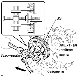
Using SST, remove the crankshaft pulley and pulley bolt.
- SST
- 09950-50013(09951-05010,09952-05010,09953-05020,09954-05021)
- УКАЗАНИЕ:
- If necessary, remove the pulley and pulley bolt using SST.
| 12. REMOVE NO. 1 CHAIN TENSIONER ASSEMBLY |
Remove the 2 nuts, bracket, tensioner and gasket.
- ПРИМЕЧАНИЕ:
- Do not turn the crankshaft without the chain tensioner.
| 13. REMOVE CRANKSHAFT POSITION SENSOR |
Remove the bolt and sensor.
| 14. REMOVE ENGINE OIL PRESSURE SWITCH ASSEMBLY |
Using a 24 mm deep socket wrench, remove the engine oil pressure switch assembly.
| 15. REMOVE NO. 1 TAPER SCREW PLUG |
Remove the taper screw plug.
| 16. REMOVE KNOCK CONTROL SENSOR |
Remove the bolt and sensor.
| 17. REMOVE ENGINE COOLANT TEMPERATURE SENSOR |
Remove the engine water temperature sensor.
Remove the gasket from the engine water temperature sensor.
| 18. REMOVE OIL FILTER SUB-ASSEMBLY |
Using SST, remove the oil filter.
- SST
- 09228-06501
- УКАЗАНИЕ:
- Place a container for oil to be drained before removing the oil filter.
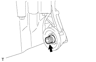
Using a 12 mm socket hexagon wrench, remove the union.
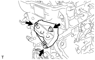
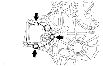
| 19. REMOVE TIMING CHAIN COVER SUB-ASSEMBLY |
Remove the 3 bolts and engine mounting bracket.
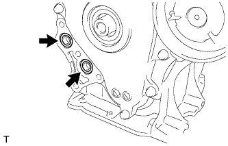
Remove the 4 bolts and oil filter bracket.
Remove the 2 O-rings.
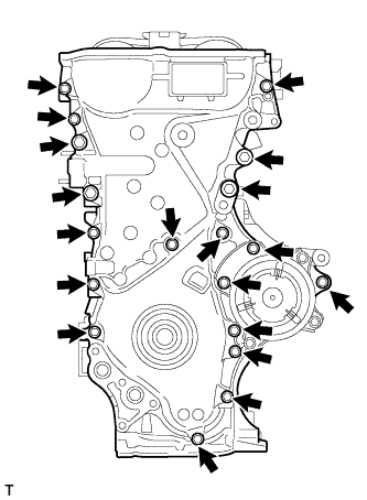
Remove the 19 bolts.
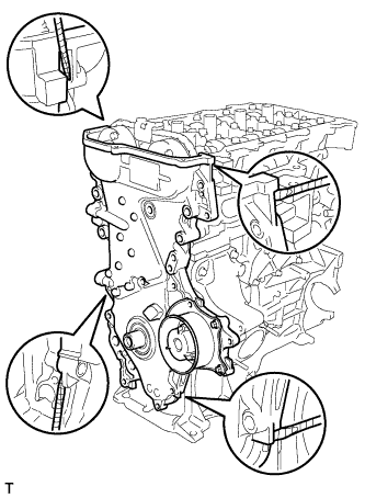
Remove the timing chain cover by prying between the timing chain cover and cylinder head or cylinder block with a screwdriver.
- ПРИМЕЧАНИЕ:
- Be careful not to damage the contact surfaces of the timing chain cover, cylinder block, and cylinder head.
- УКАЗАНИЕ:
- Tape the screwdriver tip before use.
Remove the 3 O-rings.
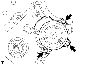
Remove the 3 bolts and water pump.
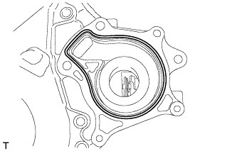
Remove the gasket.
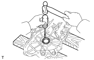
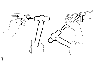
| 20. REMOVE TIMING CHAIN COVER OIL SEAL |
Using a screwdriver and hammer, remove the oil seal.
- ПРИМЕЧАНИЕ:
- Be careful not to damage the timing chain case oil seal.
- УКАЗАНИЕ:
- Tape the screwdriver tip before use.
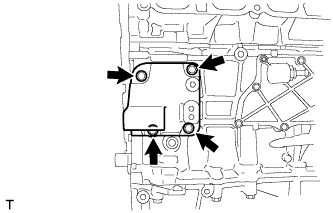
| 21. REMOVE WATER INLET HOUSING |
Remove the 3 bolts, gasket and water inlet housing.
| 22. REMOVE NO. 1 GENERATOR BRACKET |
Remove the 4 bolts and No. 1 generator bracket.
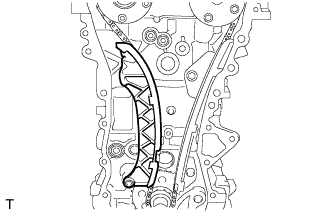
| 23. REMOVE CHAIN TENSIONER SLIPPER |
Remove the chain tensioner slipper.
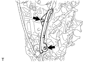
| 24. REMOVE NO. 1 CHAIN VIBRATION DAMPER |
Remove the 2 bolts and No. 1 chain vibration damper.
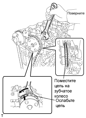
| 25. REMOVE CHAIN SUB-ASSEMBLY |
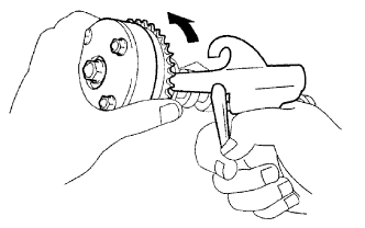
Hold the hexagonal portion of the camshaft with a wrench and turn the camshaft timing gear assembly counterclockwise to loosen the chain between the camshaft timing gears.
With the chain loosened, release the chain from the camshaft timing gear assembly and place it on the camshaft timing gear assembly.
- УКАЗАНИЕ:
- Be sure to release the chain from the sprocket completely.
Turn the camshaft clockwise to return it to the original position and remove the chain.
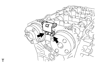
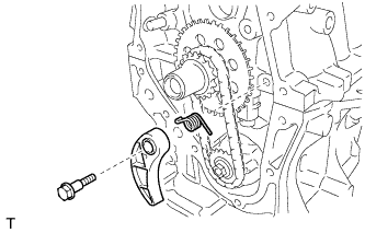
| 26. REMOVE NO. 2 CHAIN VIBRATION DAMPER |
Remove the 2 bolts and No. 2 chain vibration damper.
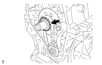
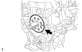
| 27. REMOVE CRANKSHAFT TIMING SPROCKET |
Remove the crankshaft timing sprocket.
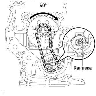
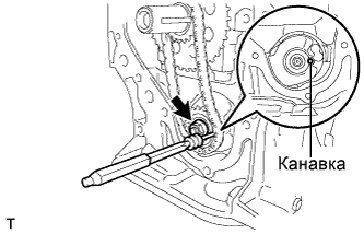
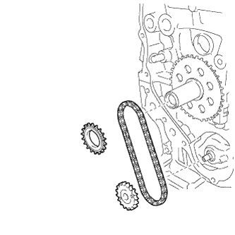
| 28. REMOVE NO. 2 CHAIN SUB-ASSEMBLY |
Temporarily tighten the crank pulley bolt.
Turn the crankshaft 90° clockwise to align the adjusting hole of the oil pump drive shaft sprocket with the groove of the oil pump.
- ПРИМЕЧАНИЕ:
- Do not rotate the crankshaft more than 90°. If the crankshaft is rotated too much without the timing chain installed, the valves may hit the pistons and cause damage.
Remove the crank pulley bolt.
Insert a 3 mm diameter bar into the adjusting hole of the oil pump drive shaft sprocket to lock the gear in position, and then remove the nut.
Remove the bolt, chain tensioner plate, and spring.
Remove the crankshaft timing sprocket, oil pump drive shaft gear, and No. 2 chain sub-assembly.
| 29. REMOVE NO. 1 CRANKSHAFT POSITION SENSOR PLATE |
Remove the No. 1 crankshaft position sensor plate.
| 30. REMOVE CRANKSHAFT TIMING GEAR KEY |
Using a screwdriver, remove the 2 crankshaft timing gear keys.
- УКАЗАНИЕ:
- Tape the screwdriver tip before use.
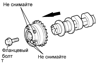
| 31. REMOVE CAMSHAFT TIMING EXHAUST GEAR ASSEMBLY |
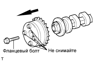
Remove the flange bolt while holding the hexagonal portion of the camshaft, and then remove the camshaft timing exhaust gear assembly.
- ПРИМЕЧАНИЕ:
- Be sure not to remove the other 4 bolts.
- Keep the camshaft timing exhaust gear assembly horizontal while removing it from the camshaft.
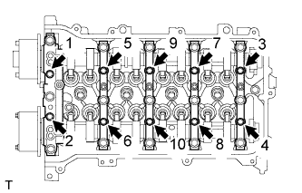
| 32. REMOVE CAMSHAFT BEARING CAP |
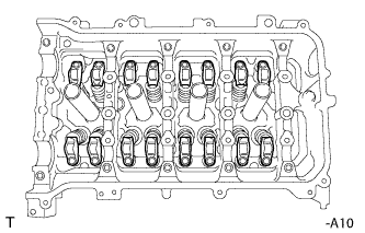
Uniformly loosen and remove the 10 bearing cap bolts in the sequence shown in the illustration.
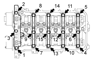
Uniformly loosen and remove the 15 bearing cap bolts in the sequence shown in the illustration.
- ПРИМЕЧАНИЕ:
- Uniformly loosen the bolts while keeping the camshaft level.
Remove the 5 bearing caps.
- УКАЗАНИЕ:
- Arrange the removed parts in the correct order.
| 33. REMOVE NO. 1 VALVE ROCKER ARM SUB-ASSEMBLY |
Remove the 16 valve rocker arms.
- УКАЗАНИЕ:
- Arrange the removed parts in the correct order.
| 34. REMOVE VALVE LASH ADJUSTER ASSEMBLY |
Remove the 16 valve lash adjusters from the cylinder head.
- УКАЗАНИЕ:
- Arrange the removed parts in the correct order.
| 35. REMOVE CAMSHAFT TIMING GEAR ASSEMBLY |
Check the lock of the camshaft timing gear.
Release the lock pin.
- ПРИМЕЧАНИЕ:
- Before removing the camshaft timing gear assembly, make sure that the lock pin has been released.
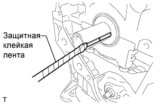
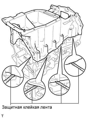
Cover the 4 oil paths of the cam journal with vinyl tape as shown in the illustration.
- УКАЗАНИЕ:
- There are 4 oil paths in the groove of the camshaft. Plug three of the paths with pieces of rubber.
Prick a hole in the tape placed on the advance side. Prick a hole in the tape placed on the retard side path, on the opposite side to that of the advance side path, as shown in the illustration.
While applying approximately 150 kPa (2.0 kgf/cm2, 22 psi) of air pressure to the oil paths, forcibly turn the camshaft timing gear assembly in the advance direction (counterclockwise).
- ПРЕДОСТЕРЕЖЕНИЕ:
- Cover the paths with a piece of cloth when applying pressure to keep oil from splashing.
- ПРИМЕЧАНИЕ:
- Do not lock the camshaft timing gear assembly. If it is locked, release the lock pin again.
- УКАЗАНИЕ:
- The camshaft timing gear assembly may be turned in the advance direction without applying any force.
- If enough air pressure cannot be applied because of air leakage from the port, releasing the lock pin may be difficult.
Remove the electrical tape and rubber pieces from the camshaft.
Install the camshafts (See page Нажмите здесь).
Remove the flange bolt while holding the hexagonal portion of the camshaft, and then remove the camshaft timing gear assembly.
- ПРИМЕЧАНИЕ:
- Before removing the camshaft timing gear, make sure that the lock pin has been released.
- Be sure not to remove the other 4 bolts.
- Keep the camshaft timing gear assembly horizontal while removing it from the camshaft.
Uniformly loosen and remove the 10 bearing cap bolts in the sequence shown in the illustration.
Uniformly loosen and remove the 15 bearing cap bolts in the sequence shown in the illustration.
- ПРИМЕЧАНИЕ:
- Uniformly loosen the bolts while keeping the camshaft level.
Remove the 5 bearing caps.
- УКАЗАНИЕ:
- Arrange the removed parts in the correct order.
Remove the camshaft.
| 37. REMOVE NO. 2 CAMSHAFT |
Remove the No. 2 camshaft.
| 38. REMOVE OIL CONTROL VALVE FILTER |
Remove the oil control valve filter.
| 39. REMOVE NO. 1 CAMSHAFT BEARING |
Remove the 2 No. 1 camshaft bearings.
| 40. REMOVE NO. 2 CAMSHAFT BEARING |
Remove the 2 No. 2 camshaft bearings.
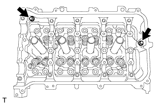
| 41. REMOVE CAMSHAFT HOUSING SUB-ASSEMBLY |
Remove the 2 bolts.
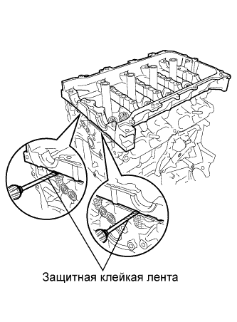
Remove the camshaft housing by prying between the cylinder head and camshaft housing with a screwdriver.
- ПРИМЕЧАНИЕ:
- Be careful not to damage the contact surfaces of the cylinder head and camshaft housing.
- УКАЗАНИЕ:
- Tape the screwdriver tip before use.
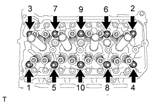
| 42. REMOVE CYLINDER HEAD SUB-ASSEMBLY |
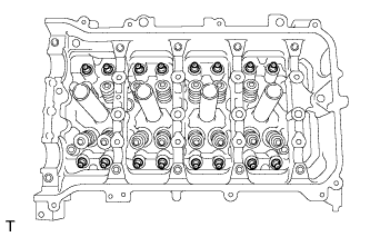
Using several steps, uniformly loosen and remove the 10 cylinder head bolts and 10 plate washers with a 10 mm bi-hexagon wrench in the sequence shown in the illustration.
- ПРИМЕЧАНИЕ:
- Head warpage or cranking could result from removing the bolts in the wrong order.
Using a screwdriver with its tip wrapped with tape, pry between the cylinder head and cylinder block, and remove the cylinder head.
- ПРИМЕЧАНИЕ:
- Be careful not to damage the contact surfaces of the cylinder head and cylinder block.
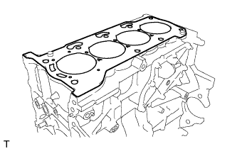
| 43. REMOVE CYLINDER HEAD GASKET |
Remove the cylinder head gasket.
| 44. REMOVE CYLINDER BLOCK WATER DRAIN COCK SUB-ASSEMBLY |
Remove the water drain cock plug from the water drain cock sub-assembly.
Remove the cylinder block water drain cock sub-assembly from the cylinder block.
| 45. REMOVE VENTILATION VALVE SUB-ASSEMBLY |
Remove the ventilation valve.
| 46. REMOVE OIL PAN DRAIN PLUG |
Remove the oil pan drain plug and gasket.
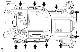
| 47. REMOVE NO. 2 OIL PAN SUB-ASSEMBLY |
Remove the 10 bolts and 2 nuts.
Insert the blade of SST between the crankcase and oil pan. Cut through the sealer and remove the oil pan.
- SST
- 09032-00100
- ПРИМЕЧАНИЕ:
- Be careful not to damage the contact surfaces of the crankcase, chain cover, and oil pan.
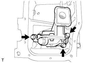
| 48. REMOVE OIL PUMP ASSEMBLY |
Remove the 3 bolts and oil pump.
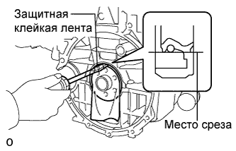
| 49. REMOVE ENGINE REAR OIL SEAL |
Using a knife, cut off the oil seal lip.
Using a screwdriver with its tip taped, pry out the oil seal.
- ПРИМЕЧАНИЕ:
- After removing the oil seal, check the crankshaft for damage. If it is damaged, smooth the surface with 400-grit sandpaper.
| 50. REMOVE STIFFENING CRANKCASE ASSEMBLY |
Uniformly loosen and remove the 11 bolts.
Using a screwdriver, remove the crankcase by prying between the crankcase and cylinder block.
- ПРИМЕЧАНИЕ:
- Be careful not to damage the contact surfaces of the crankcase and cylinder block.