Впускной Коллектор -- Установка |
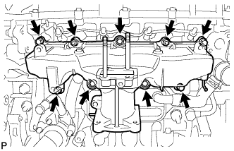
| 1. INSTALL INTAKE MANIFOLD |
Install a new gasket and the intake manifold with the 7 bolts and 2 nuts.
- Момент затяжки:
- 26 Н*м{265 кгс*см, 19 фунт-сила-футов}
 |
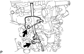
| 2. INSTALL OIL DIPSTICK GUIDE |
Install a new O-ring to the dipstick guide.
Install the dipstick guide with the 2 bolts.
- Момент затяжки:
- 33 Н*м{337 кгс*см, 24 фунт-сила-футов}
 |
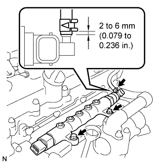
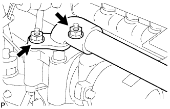
| 3. INSTALL COMMON RAIL ASSEMBLY |
Install the intake manifold insulator and common rail with the 2 bolts.
- Момент затяжки:
- 21 Н*м{210 кгс*см, 15 фунт-сила-футов}
 |
Using pliers, grip the claws of the clip and slide the clip to connect the fuel hose as shown in the illustration.
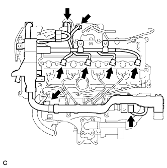
| 4. INSTALL NO. 1 INJECTION PIPE SUB-ASSEMBLY |
- ПРИМЕЧАНИЕ:
- In a case where the common rail is replaced, the injection pipes must also be replaced.
Temporarily install the 4 injection pipes.
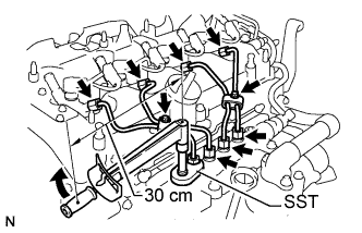 |
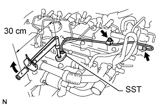
Using SST, first tighten the nut at the common rail end of the injection pipe.
- SST
- 09023-38401
- Момент затяжки:
- 27 Н*м{275 кгс*см, 20 фунт-сила-футов}
- УКАЗАНИЕ:
- Use of proper SST is required to ensure that the correct torque is applied to the injection pipe nut.
- Use a torque wrench with a fulcrum length of 30 cm (11.81 in.).
- Make sure that the pipe is not deformed or twisted during installation.
If the pipe is deformed or twisted, or if it cannot be installed properly, replace the pipe with a new one.
Using SST, tighten the nut at the injector end of the injection pipe.
- SST
- 09023-38401
- Момент затяжки:
- 27 Н*м{275 кгс*см, 20 фунт-сила-футов}
- УКАЗАНИЕ:
- Use of proper SST is required to ensure that the correct torque is applied to the injection pipe nut.
- Use a torque wrench with a fulcrum length of 30 cm (11.81 in.).
- Make sure that the pipe is not deformed or twisted during installation.
If the pipe is deformed or twisted, or if it cannot be installed properly, replace the pipe with a new one.
| 5. INSTALL NO. 2 INJECTION PIPE SUB-ASSEMBLY |
- УКАЗАНИЕ:
- Perform the same procedure as for the No. 1 injection pipe.
| 6. INSTALL NO. 3 INJECTION PIPE SUB-ASSEMBLY |
- УКАЗАНИЕ:
- Perform the same procedure as for the No. 1 injection pipe.
| 7. INSTALL NO. 4 INJECTION PIPE SUB-ASSEMBLY |
- УКАЗАНИЕ:
- Perform the same procedure as for the No. 1 injection pipe.
Install the 4 injection pipe clamps with the 2 bolts.
- Момент затяжки:
- 5.0 Н*м{51 кгс*см, 44 фунт-сила-дюймов}
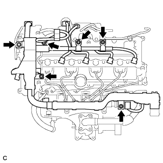
| 8. INSTALL FUEL INLET PIPE SUB-ASSEMBLY |
- ПРИМЕЧАНИЕ:
- In a case where the common rail is replaced, the fuel inlet pipe must also be replaced.
Temporarily install the fuel inlet pipe with the 2 clamps and nut.
 |
Using SST, first tighten the nut at the common rail end of the fuel inlet pipe.
- SST
- 09023-38401
- Момент затяжки:
- 27 Н*м{275 кгс*см, 15 фунт-сила-футов}
- УКАЗАНИЕ:
- Use of proper SST is required to ensure that the correct torque is applied to the fuel inlet pipe nut.
- Use a torque wrench with a fulcrum length of 30 cm (11.81 in.).
- Make sure that the pipe is not deformed or twisted during installation.
If the pipe is deformed or twisted, or if it cannot be installed properly, replace the pipe with a new one.
Using SST, tighten the nut at the injection or supply pump end of the fuel inlet pipe.
- SST
- 09023-38401
- Момент затяжки:
- 27 Н*м{275 кгс*см, 20 фунт-сила-футов}
- УКАЗАНИЕ:
- Use of proper SST is required to ensure that the correct torque is applied to the fuel inlet pipe nut.
- Use a torque wrench with a fulcrum length of 30 cm (11.81 in.).
- Make sure that the pipe is not deformed or twisted during installation.
If the pipe is deformed or twisted, or if it cannot be installed properly, replace the pipe with a new one.
Tighten the fuel inlet pipe clamp nut.
- Момент затяжки:
- 5.0 Н*м{51 кгс*см, 44 фунт-сила-дюймов}
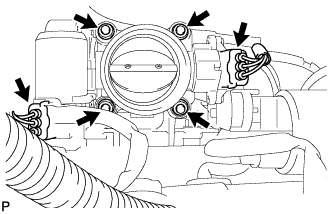
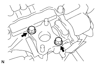
| 9. INSTALL DIESEL THROTTLE BODY ASSEMBLY |
Install a new gasket and the diesel throttle body with the 2 nuts and 2 bolts.
- Момент затяжки:
- 21 Н*м{214 кгс*см, 15 фунт-сила-футов}
 |
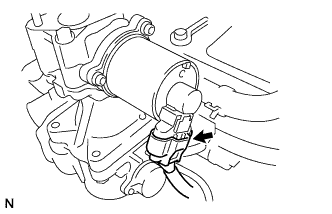
Connect the throttle position sensor connector.
Connect the throttle motor connector.
| 10. INSTALL NO. 4 AIR HOSE |
Insert the No. 4 air hose to the diesel throttle body.
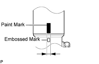
Insert the No. 2 air tube to the No. 4 air hose as described below.
Align the embossed mark of the No. 2 air tube within the paint mark of the No. 4 air hose.
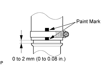
Temporarily install the 2 hose clamps.
- ПРИМЕЧАНИЕ:
- Each hose clamp should be installed so that the paint mark can be seen on either side of the clamp band as shown in the illustration.
Install the No. 2 air tube with the bolt.
- Момент затяжки:
- 48 Н*м{489 кгс*см, 35 фунт-сила-футов}
 |
Tighten the 2 hose clamps.
- Момент затяжки:
- 6.3 Н*м{64 кгс*см, 56 фунт-сила-дюймов}
Connect the sensor connector.
| 11. INSTALL NO. 3 AIR HOSE |
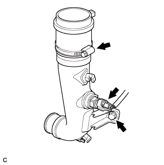
Install the No. 3 air hose.
Tighten the hose clamp.
- Момент затяжки:
- 6.3 Н*м{64 кгс*см, 56 фунт-сила-дюймов}
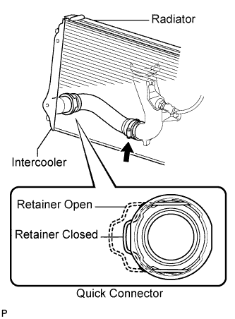
Connect the No. 3 air hose to the intercooler.
- ПРИМЕЧАНИЕ:
- Check that the retainer is closed when the connector is inserted.
- If replacing or reusing the hose, check for deposits in the intercooler and air hose. If necessary, wipe off the deposits.
- If replacing or reusing the hose, apply fresh oil to the O-ring.
- The connectors should be inserted until a clicking sound indicating that they are completely connected is heard. Then, check that the connectors cannot be disconnected by pulling on them.
- Do not use a quick connector that has been dropped.
| 12. INSTALL VACUUM TRANSMITTING HOSE ASSEMBLY |
Connect the vacuum transmitting hose to the No. 2 air tube.
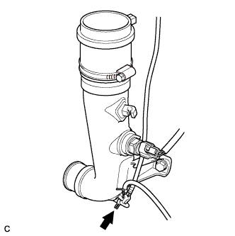 |
Install the vacuum transmitting hose to the 3 clamps.
 |
| 13. INSTALL EGR VALVE ASSEMBLY |
Install a new gasket and the EGR valve with the 2 bolts.
- Момент затяжки:
- 24 Н*м{245 кгс*см, 18 фунт-сила-футов}
 |
Connect the EGR valve connector.
 |
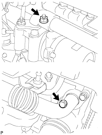
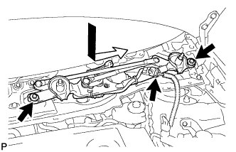
| 14. INSTALL NO. 2 EGR PIPE SUB-ASSEMBLY |
Temporarily install 2 new gaskets and the No. 2 EGR pipe with the nut and bolt as shown in the illustration.
- УКАЗАНИЕ:
- Note the direction of the gaskets.
- Install the pipe with the claws facing the pipe as shown in the illustration.
 |
Temporarily install the bolt and nut as shown in the illustration.
 |
Tighten the 2 bolts holding the EGR pipe to the cylinder head.
- Момент затяжки:
- 24 Н*м{245 кгс*см, 18 фунт-сила-футов}
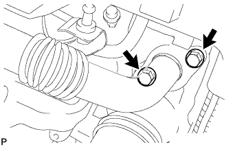 |
Tighten the 2 nuts holding the EGR pipe to the EGR valve.
- Момент затяжки:
- 24 Н*м{245 кгс*см, 18 фунт-сила-футов}
 |
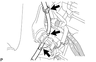
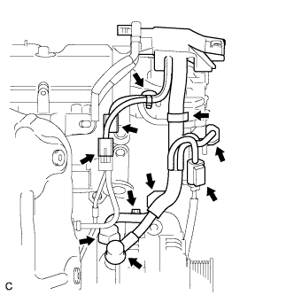
| 15. CONNECT ENGINE WIRE |
Connect the generator wire to terminal B with the nut and bolt.
- Момент затяжки:
- for Nut:
- 9.8 Н*м{100 кгс*см, 87 фунт-сила-дюймов}
- for Bolt:
- 8.4 Н*м{86 кгс*см, 74 фунт-сила-дюймов}
 |
Install the terminal cap.
Connect the 2 clamps.
Connect the 5 connectors.
Install the bolt.
- Момент затяжки:
- 8.3 Н*м{85 кгс*см, 74 фунт-сила-дюймов}
 |
Connect the 2 clamps.
Connect the 3 connectors.
Connect the 8 connectors.
 |
Install the bolt and 5 nuts.
- Момент затяжки:
- 8.3 Н*м{85 кгс*см, 74 фунт-сила-дюймов}
 |
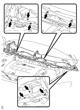
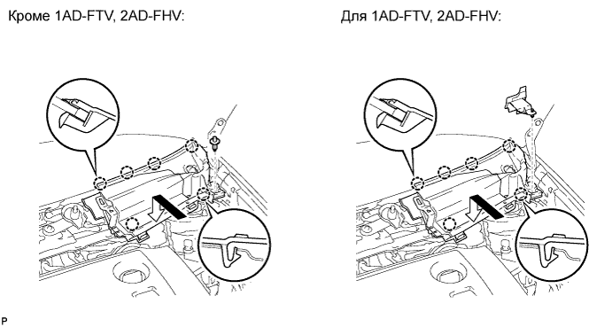
| 16. INSTALL COWL TOP PANEL OUTER |
Установите наружную верхнюю панель кожуха и закрепите ее 8 болтами.
- Момент затяжки:
- 8,8 Н*м{90 кгс*см, 78 фунт-сила-дюймов}
 |
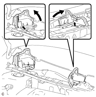
Отогните правую водозащитную пластину и брызгозащитное уплотнение воздуховода отопителя № 1 и отсоедините все зажимы, как показано на рисунке.
 |
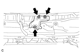
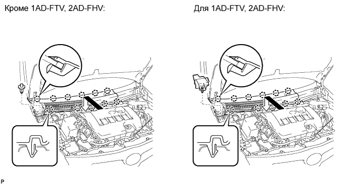
| 17. INSTALL COWL BODY MOUNTING REINFORCEMENT LH |
Установите левый усилитель крепления кожуха к кузову и закрепите его 3 болтами.
- Момент затяжки:
- 8,8 Н*м{90 кгс*см, 78 фунт-сила-дюймов}
 |
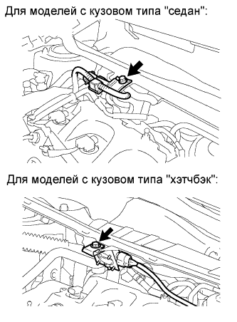
| 18. INSTALL DIFFERENTIAL PRESSURE SENSOR ASSEMBLY |
Установите дифференциальный датчик давления в сборе на наружную верхнюю панель кожуха и закрепите его болтом.
- Момент затяжки:
- 5,5 Н*м{56 кгс*см, 49 фунт-сила-дюймов}
 |
| 19. INSTALL WINDSHIELD WIPER MOTOR AND LINK ASSEMBLY |
Установите электродвигатель стеклоочистителя ветрового стекла с тягой в сборе и закрепите его 2 болтами.
- Момент затяжки:
- 5,5 Н*м{56 кгс*см, 49 фунт-сила-дюймов}
 |
Подсоедините разъем.
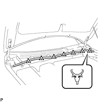
| 20. INSTALL COWL TOP VENTILATOR LOUVER LH |
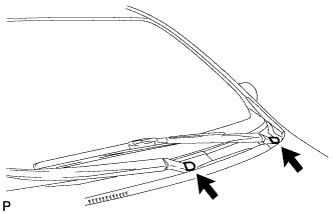
Введите в зацепление фиксатор и 6 захватов и установите левую вентиляционную решетку в верхней части кожуха.
| 21. INSTALL COWL TOP VENTILATOR LOUVER RH |
Введите в зацепление фиксатор и 11 захватов и установите правую вентиляционную решетку в верхней части кожуха.
| 22. INSTALL HOOD TO COWL TOP SEAL |
Освободите 7 фиксаторов и отсоедините верхнее уплотнение между капотом и кожухом.
 |
| 23. INSTALL FRONT WIPER ARM AND BLADE ASSEMBLY RH |
Приведите в действие стеклоочиститель и остановите электродвигатель стеклоочистителя ветрового стекла в положении автоматического ограничения хода.
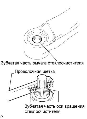
Очистите зубчатую часть рычага стеклоочистителя.
 |
При повторной установке:
Почистите зубчатую часть оси вращения стеклоочистителя проволочной щеткой.
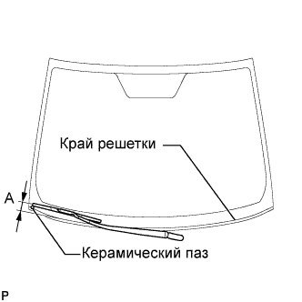
Установите правый рычаг переднего стеклоочистителя со щеткой в сборе, как показано на рисунке, и закрепите их гайкой.
- Момент затяжки:
- 26 Н*м{265 кгс*см, 19 фунт-сила-футов}
- УКАЗАНИЕ:
- Удерживайте шарнир рычага рукой, чтобы затянуть гайку.
Участок Измерение А 17,5–32,5 мм (0,39–1,57 дюйма)
 |
| 24. INSTALL FRONT WIPER ARM AND BLADE ASSEMBLY LH |
Приведите в действие стеклоочиститель и остановите электродвигатель стеклоочистителя ветрового стекла в положении автоматического ограничения хода.
Очистите зубчатую часть рычага стеклоочистителя.
|
При повторной установке:
Почистите зубчатую часть оси вращения стеклоочистителя проволочной щеткой.
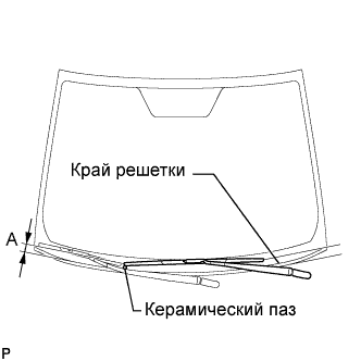
Установите левый рычаг переднего стеклоочистителя со щеткой в сборе, как показано на рисунке, и закрепите их гайкой.
- Момент затяжки:
- 26 Н*м{265 кгс*см, 19 фунт-сила-футов}
- УКАЗАНИЕ:
- Удерживайте шарнир рычага рукой, чтобы затянуть гайку.
Участок Измерение А 25,5–40,5 мм (0,71–1,89 дюйма)
 |
Приведите в действие передние стеклоочистители, одновременно распыляя омывающую жидкость на ветровое стекло. Убедитесь, что передние стеклоочистители работают надлежащим образом и не задевают кузов автомобиля.
| 25. INSTALL FRONT WIPER ARM HEAD CAP |
Установите 2 крышки.
 |
| 26. CONNECT CABLE TO NEGATIVE BATTERY TERMINAL |
| 27. INSTALL REAR ENGINE UNDER COVER RH |
| 28. INSTALL NO. 1 ENGINE UNDER COVER |
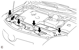
| 29. INSTALL NO. 1 ENGINE COVER |
Attach the 4 clips to install the engine cover.
- ПРИМЕЧАНИЕ:
- Line up the 4 grommets using the oil filler cap and oil dipstick as guides.
- Push down on the four locations shown to install the cover.
 |
| 30. INSTALL UPPER RADIATOR AIR DEFLECTOR |
Установите 6 фиксаторов и верхний воздушный отражатель радиатора.
 |