Двигатель В Сборе Снятие. Corolla Auris
Двигатель. COROLLA, AURIS. ZZE150 ZRE151,152 NDE150
DISCHARGE FUEL SYSTEM PRESSURE
ALIGN FRONT WHEELS FACING STRAIGHT AHEAD
REMOVE FRONT WHEEL
REMOVE REAR ENGINE UNDER COVER LH
REMOVE REAR ENGINE UNDER COVER RH
REMOVE NO. 1 ENGINE UNDER COVER
REMOVE NO. 2 ENGINE UNDER COVER
DRAIN ENGINE COOLANT
DRAIN MANUAL TRANSAXLE OIL (for Manual Transaxle)
DRAIN AUTOMATIC TRANSAXLE FLUID (for Automatic Transaxle)
REMOVE UPPER RADIATOR AIR DEFLECTOR
REMOVE NO. 2 CYLINDER HEAD COVER
REMOVE AIR CLEANER CAP SUB-ASSEMBLY
REMOVE AIR CLEANER CASE
REMOVE BATTERY
REMOVE BATTERY CARRIER
SEPARATE RADIATOR HOSE INLET
SEPARATE RADIATOR HOSE OUTLET
DISCONNECT TRANSMISSION CONTROL CABLE ASSEMBLY (for Manual Transaxle)
DISCONNECT TRANSMISSION CONTROL CABLE ASSEMBLY (for Automatic Transaxle)
DISCONNECT OIL COOLER HOSE (for Automatic Transaxle)
DISCONNECT HEATER OUTLET WATER HOSE
DISCONNECT HEATER INLET WATER HOSE
DISCONNECT FUEL TUBE SUB-ASSEMBLY
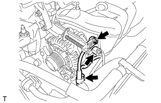
REMOVE V-RIBBED BELT
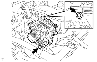
REMOVE GENERATOR ASSEMBLY
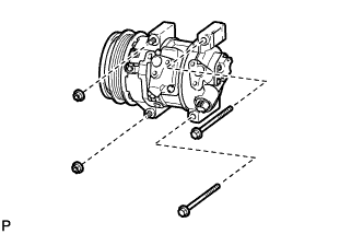
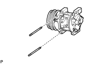
SEPARATE COMPRESSOR WITH PULLEY ASSEMBLY (w/ Air Conditioning System)
SEPARATE CLUTCH RELEASE CYLINDER ASSEMBLY (for Manual Transaxle)
DISCONNECT WIRE HARNESS
SECURE STEERING WHEEL
REMOVE COLUMN HOLE COVER SILENCER SHEET
SEPARATE NO. 2 STEERING INTERMEDIATE SHAFT ASSEMBLY
DISCONNECT NO. 1 STEERING COLUMN HOLE COVER SUB-ASSEMBLY
DISCONNECT HEATED OXYGEN SENSOR
REMOVE FRONT EXHAUST PIPE ASSEMBLY
REMOVE FRONT AXLE HUB LH NUT
REMOVE FRONT AXLE HUB RH NUT
DISCONNECT FRONT SPEED SENSOR LH
DISCONNECT FRONT SPEED SENSOR RH
SEPARATE TIE ROD END SUB-ASSEMBLY LH
SEPARATE TIE ROD END SUB-ASSEMBLY RH
SEPARATE FRONT STABILIZER LINK ASSEMBLY LH
SEPARATE FRONT STABILIZER LINK ASSEMBLY RH
SEPARATE FRONT SUSPENSION ARM SUB-ASSEMBLY LOWER NO. 1 LH
SEPARATE FRONT SUSPENSION ARM SUB-ASSEMBLY LOWER NO. 1 RH
SEPARATE STEERING KNUCKLE WITH AXLE HUB LH
SEPARATE STEERING KNUCKLE WITH AXLE HUB RH
REMOVE FRONT DRIVE SHAFT ASSEMBLY LH
REMOVE FRONT DRIVE SHAFT ASSEMBLY RH
REMOVE FLYWHEEL HOUSING UNDER COVER (for Automatic Transaxle)
REMOVE DRIVE PLATE AND TORQUE CONVERTER CLUTCH SETTING BOLT (for Automatic Transaxle)
REMOVE ENGINE FRONT MOUNTING BRACKET REINFORCEMENT LOWER
REMOVE FRONT SUSPENSION MEMBER REINFORCEMENT LH
REMOVE FRONT SUSPENSION MEMBER REINFORCEMENT RH
REMOVE FRONT SUSPENSION MEMBER REAR BRACE LH
REMOVE FRONT SUSPENSION MEMBER REAR BRACE RH
REMOVE FRONT SUSPENSION CROSSMEMBER SUB-ASSEMBLY
REMOVE FRONT CROSSMEMBER
REMOVE ENGINE ASSEMBLY WITH TRANSAXLE
REMOVE REAR ENGINE MOUNTING INSULATOR
INSTALL ENGINE HANGER
REMOVE FLYWHEEL HOUSING SIDE COVER
REMOVE STARTER ASSEMBLY
REMOVE MANUAL TRANSAXLE ASSEMBLY (for Manual Transaxle)
REMOVE AUTOMATIC TRANSAXLE ASSEMBLY (for Automatic Transaxle)
REMOVE CLUTCH COVER ASSEMBLY (for Manual Transaxle)
REMOVE CLUTCH DISC ASSEMBLY (for Manual Transaxle)
REMOVE FLYWHEEL SUB-ASSEMBLY (for Manual Transaxle)
REMOVE DRIVE PLATE AND RING GEAR SUB-ASSEMBLY (for Automatic Transaxle)
REMOVE ENGINE WIRE
INSTALL ENGINE STAND
REMOVE FAN BELT ADJUSTING BAR
REMOVE INTAKE MANIFOLD
REMOVE FUEL TUBE SUB-ASSEMBLY
REMOVE FUEL DELIVERY PIPE SUB-ASSEMBLY
REMOVE FUEL INJECTOR ASSEMBLY
REMOVE IGNITION COIL ASSEMBLY
REMOVE OIL LEVEL GAUGE SUB-ASSEMBLY
REMOVE NO. 1 EXHAUST MANIFOLD HEAT INSULATOR
REMOVE MANIFOLD STAY
REMOVE EXHAUST MANIFOLD
REMOVE VENTILATION HOSE
SEPARATE NO. 3 WATER BY-PASS HOSE
REMOVE NO. 1 WATER BY-PASS PIPE
REMOVE WATER BY-PASS HOSE
REMOVE WATER INLET HOSE
REMOVE WATER INLET
REMOVE THERMOSTAT
REMOVE RADIO SETTING CONDENSER
REMOVE ENGINE COOLANT TEMPERATURE SENSOR
REMOVE KNOCK CONTROL SENSOR
REMOVE ENGINE OIL PRESSURE SWITCH ASSEMBLY
Двигатель В Сборе -- Снятие |
| 1. DISCHARGE FUEL SYSTEM PRESSURE |
- УКАЗАНИЕ:
- See page Нажмите здесь.
| 2. ALIGN FRONT WHEELS FACING STRAIGHT AHEAD |
| 4. REMOVE REAR ENGINE UNDER COVER LH |
| 5. REMOVE REAR ENGINE UNDER COVER RH |
| 6. REMOVE NO. 1 ENGINE UNDER COVER |
| 7. REMOVE NO. 2 ENGINE UNDER COVER |
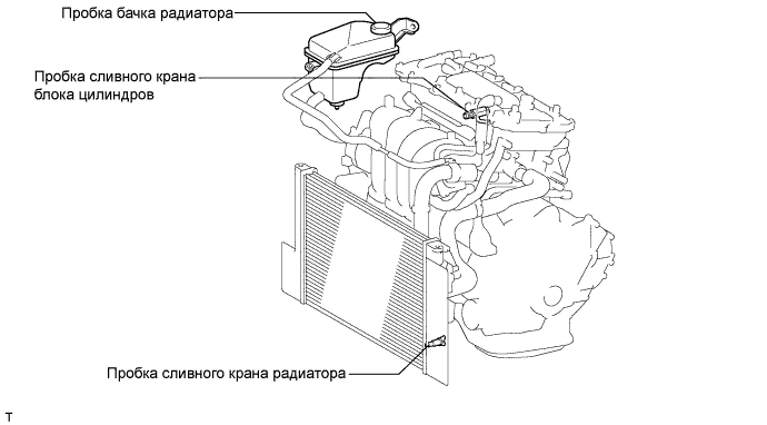
Loosen the radiator drain cock plug.
- УКАЗАНИЕ:
- Collect the coolant in a container and dispose of it according to the regulations in your area.
Remove the radiator reservoir cap.
- ПРЕДОСТЕРЕЖЕНИЕ:
- Do not remove the radiator reservoir cap while the engine and radiator are still hot.
- Pressurized, hot engine coolant and steam may be released and cause serious burns.
Loosen the cylinder block drain cock plug.
- УКАЗАНИЕ:
- The plug is on the backside of the generator on the exhaust manifold side.
| 9. DRAIN MANUAL TRANSAXLE OIL (for Manual Transaxle) |
- УКАЗАНИЕ:
- See page Нажмите здесь for C66.
| 10. DRAIN AUTOMATIC TRANSAXLE FLUID (for Automatic Transaxle) |
- УКАЗАНИЕ:
- See page Нажмите здесь for U341E.
| 11. REMOVE UPPER RADIATOR AIR DEFLECTOR |
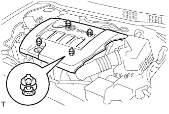
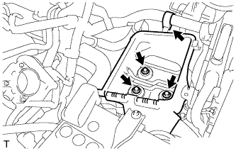
| 12. REMOVE NO. 2 CYLINDER HEAD COVER |
Hold the rear of the cover and raise it to disengage the 2 clips on the front of the cover. Continue to raise the cover to disengage the 2 clips on the front of the cover and remove the cover.
- ПРИМЕЧАНИЕ:
- Attempting to disengage both front and rear clips at the same time may cause the cover to break.
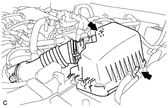
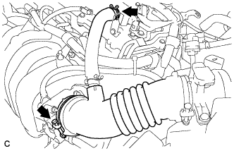
| 13. REMOVE AIR CLEANER CAP SUB-ASSEMBLY |
Disconnect the mass air flow meter connector.
Disconnect the 2 clamps.
Disconnect the band and ventilation hose, and remove the air cleaner cap sub-assembly.
| 14. REMOVE AIR CLEANER CASE |
Separate the air cleaner filter element from the air cleaner.
Remove the 3 bolts from the air cleaner case.
Disconnect the battery terminal.
Remove the bolt and loosen the nut.
Remove the battery.
| 16. REMOVE BATTERY CARRIER |
Separate the wire harness clamp from the battery carrier.
Remove the 2 bolts.
Separate the radiator pipe from the battery carrier.
Remove the 4 bolts and battery carrier.
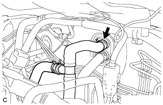
| 17. SEPARATE RADIATOR HOSE INLET |
Separate the radiator hose from the cylinder head.
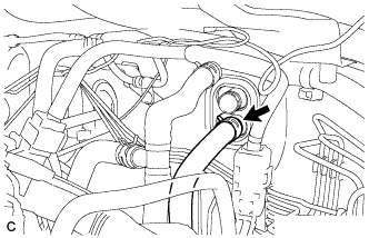
| 18. SEPARATE RADIATOR HOSE OUTLET |
Separate the radiator hose from the water inlet hose.
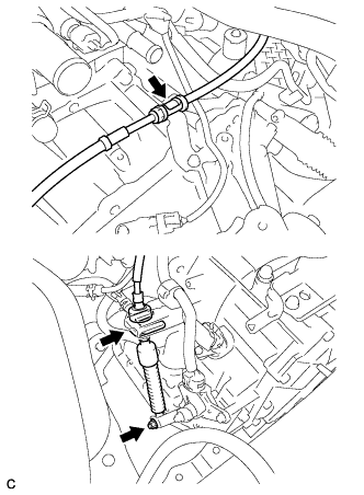
| 19. DISCONNECT TRANSMISSION CONTROL CABLE ASSEMBLY (for Manual Transaxle) |
Remove the 2 clips and disconnect the 2 cables from the transaxle.
Remove the 2 clips and disconnect the 2 cables from the control cable bracket.
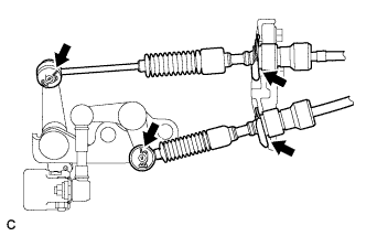
| 20. DISCONNECT TRANSMISSION CONTROL CABLE ASSEMBLY (for Automatic Transaxle) |
Disconnect the control cable from the control cable support.
Remove the nut and disconnect the control cable from the control shaft lever.
Remove the clip and disconnect the control cable from the control cable bracket.
Remove the bolt and disconnect the clamp of the control cable.
| 21. DISCONNECT OIL COOLER HOSE (for Automatic Transaxle) |
Disconnect the 2 oil cooler hoses from the automatic transaxle.
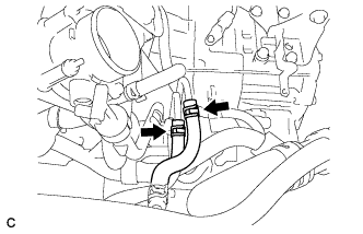
| 22. DISCONNECT HEATER OUTLET WATER HOSE |
Disconnect the heater outlet water hose from the heater unit.
| 23. DISCONNECT HEATER INLET WATER HOSE |
Disconnect the heater inlet water hose from the heater unit.
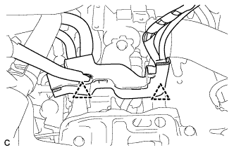
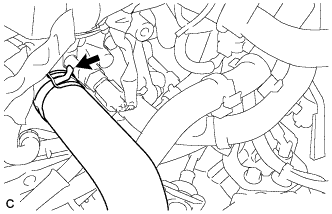
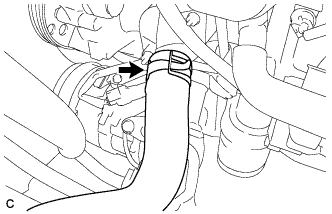
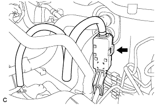
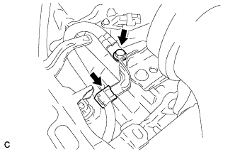
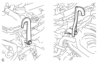
| 24. DISCONNECT FUEL TUBE SUB-ASSEMBLY |
Release the claw and remove the No. 1 fuel pipe clamp.
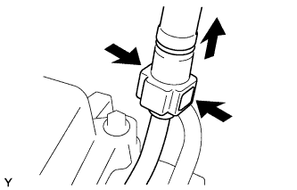
Pinch the retainer as illustrated, then pull the fuel tube connector out of the pipe.
- ПРИМЕЧАНИЕ:
- Remove any dirt and foreign matter from the fuel tube connector before performing this work.
- Do not allow any scratches or foreign matter on the parts when disconnecting, as the fuel tube connector has the O-rings that seal the pipe.
- Perform this work by hand. Do not use any tools.
- Do not forcibly bend, kink or twist the nylon tube.
- Protect the disconnected parts by covering them with vinyl bags after disconnecting the fuel tube.
- If the fuel tube connector and pipe are stuck, push and pull to release them.
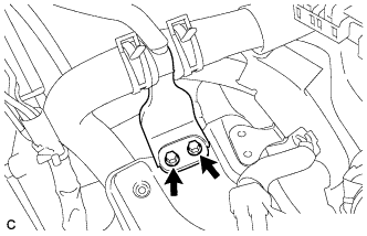
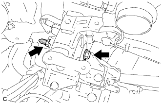
Loosen bolts A and B.
Loosen bolt C, then remove the V-ribbed belt.
- ПРИМЕЧАНИЕ:
- Do not loosen bolt D.
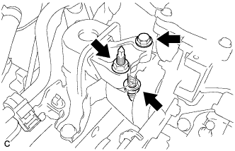
| 26. REMOVE GENERATOR ASSEMBLY |
Remove the terminal cap.
Remove the nut and disconnect the wire harness from terminal B.
Disconnect the connector and harness clamp.
Remove the 2 bolts and generator assembly.
Remove the bolt and wire harness clamp bracket.
| 27. SEPARATE COMPRESSOR WITH PULLEY ASSEMBLY (w/ Air Conditioning System) |
Disconnect the connector.
Remove the 2 bolts and 2 nuts.
Using a "TORX" socket wrench (E8), remove the 2 stud bolts and compressor assembly with pulley.
- УКАЗАНИЕ:
- Secure the compressor and hoses off to the side instead of discharging the A/C system.
| 28. SEPARATE CLUTCH RELEASE CYLINDER ASSEMBLY (for Manual Transaxle) |
Remove the 5 bolts and clutch cube bracket, and separate the clutch release cylinder assembly.
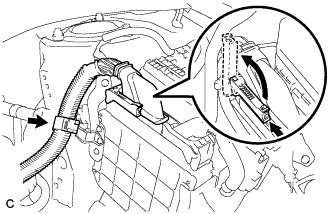
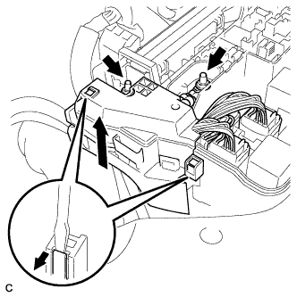
| 29. DISCONNECT WIRE HARNESS |
Pull up the lever and disconnect the connector of the engine control computer.
Remove the 2 nuts.
Remove the connector and 2 clamps from the engine room junction block and disconnect the wire harness.
Remove the bolt and clamp (for Manual Transaxle).
Remove the bolt and clamp. (for Automatic Transaxle).
Disconnect all the wire harnesses and connectors.
Make sure that no wire harness is connected between the body and engine.
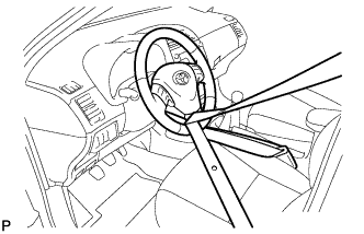
| 30. SECURE STEERING WHEEL |
Для предотвращения вращения рулевого колеса закрепите его ремнем безопасности.
- УКАЗАНИЕ:
- Эта операция позволяет предотвратить повреждение витого кабеля.
| 31. REMOVE COLUMN HOLE COVER SILENCER SHEET |
Оттяните напольный коврик, освободите 2 фиксатора и снимите шумоизолирующую накладку кожуха выходного отверстия рулевой колонки.
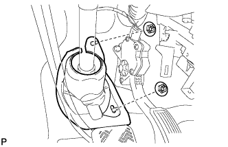
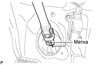
| 32. SEPARATE NO. 2 STEERING INTERMEDIATE SHAFT ASSEMBLY |
Выверните болт.
- ПРИМЕЧАНИЕ:
- Не отсоединяйте промежуточный вал № 2 рулевого управления в сборе от промежуточного вала рулевого управления.
Нанесите метки на промежуточный вал № 2 рулевого управления в сборе и промежуточный вал рулевого управления.
Отсоедините промежуточный вал № 2 рулевого управления в сборе от промежуточного вала рулевого управления.
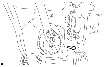
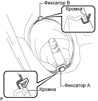
| 33. DISCONNECT NO. 1 STEERING COLUMN HOLE COVER SUB-ASSEMBLY |
Снимите фиксатор A и кожух выходного отверстия рулевой колонки № 1 в сборе и отделите фиксатор B от кузова.
- ПРИМЕЧАНИЕ:
- Не допускайте повреждения фиксаторов A и B.
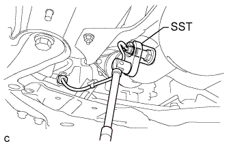
| 34. DISCONNECT HEATED OXYGEN SENSOR |
Disconnect the oxygen sensor connector.
Using SST, remove the oxygen sensor from the front exhaust pipe assembly.
- SST
- 09224-00010
- ПРИМЕЧАНИЕ:
- Do not damage the oxygen sensor.
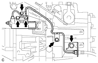
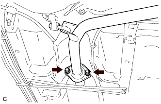
| 35. REMOVE FRONT EXHAUST PIPE ASSEMBLY |
Remove the 2 bolts and 2 compression springs.
Remove the 2 bolts and 2 compression springs.
Remove the exhaust pipe support, and then remove the front exhaust pipe assembly.
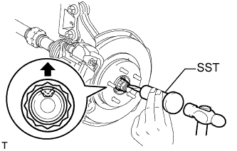
| 36. REMOVE FRONT AXLE HUB LH NUT |
С помощью SST и молотка освободите накерненную часть гайки ступицы переднего колеса.
- SST
- 09930-00010
- ПРИМЕЧАНИЕ:
- Полностью освободите накерненную часть гайки ступицы переднего колеса, иначе можно повредить винт приводного вала.
Включив тормоза, снимите гайку ступицы переднего колеса.
| 37. REMOVE FRONT AXLE HUB RH NUT |
- УКАЗАНИЕ:
- Perform the same procedure for the LH side.
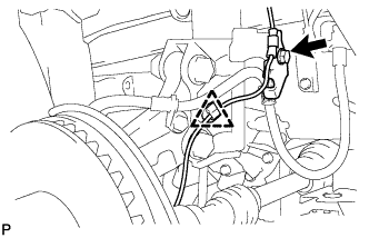
| 38. DISCONNECT FRONT SPEED SENSOR LH |
Выверните болт, снимите зажим и отсоедините передний датчик частоты вращения.
- ПРИМЕЧАНИЕ:
- Убедитесь в том, что передний датчик частоты вращения полностью отсоединен от переднего амортизатора с цилиндрической винтовой пружиной.
Выверните болт и отсоедините передний датчик частоты вращения от поворотного кулака.
- ПРИМЕЧАНИЕ:
- Не допускайте попадания на наконечник датчика посторонних частиц.
- Будьте осторожны, чтобы не повредить передний датчик частоты вращения.
- Каждый раз при снятии датчика частоты вращения очищайте установочное отверстие датчика и расположенные рядом поверхности.
| 39. DISCONNECT FRONT SPEED SENSOR RH |
- УКАЗАНИЕ:
- Perform the same procedure for the LH side.
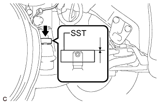
| 40. SEPARATE TIE ROD END SUB-ASSEMBLY LH |
Снимите шплинт и отверните гайку.
Установите SST на наконечник рулевой тяги.
- SST
- 09960-20010(09961-02060)
- ПРИМЕЧАНИЕ:
- Убедитесь, что верхние концы наконечника рулевой тяги и SST выровнены.
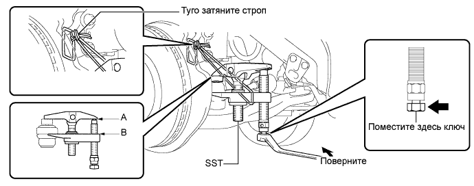
При помощи SST отсоедините наконечник тяги от поворотного кулака.
- SST
- 09960-20010(09961-02010)
- ПРИМЕЧАНИЕ:
- При закреплении SST на поворотном кулаке обязательно привяжите строп SST, чтобы он не упал.
- Установите SST таким образом, чтобы линии A и B были параллельны.
- Обязательно устанавливайте ключ на деталь, указанную на рисунке.
- Старайтесь не повредить защитный кожух переднего дискового тормоза.
- Старайтесь не повредить пыльник шарового шарнира.
- Действуйте осторожно, чтобы не повредить поворотный кулак.
| 41. SEPARATE TIE ROD END SUB-ASSEMBLY RH |
- УКАЗАНИЕ:
- Perform the same procedure for the LH side.
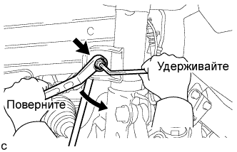
| 42. SEPARATE FRONT STABILIZER LINK ASSEMBLY LH |
Отверните гайку и отсоедините стойку стабилизатора в сборе от переднего амортизатора с цилиндрической винтовой пружиной.
- УКАЗАНИЕ:
- Если шаровой шарнир поворачивается вместе с гайкой, зафиксируйте болт пальца с помощью шестигранного ключа (на 6 мм).
| 43. SEPARATE FRONT STABILIZER LINK ASSEMBLY RH |
- УКАЗАНИЕ:
- Perform the same procedure for the LH side.
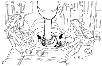
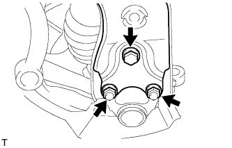
| 44. SEPARATE FRONT SUSPENSION ARM SUB-ASSEMBLY LOWER NO. 1 LH |
Выверните болт и отверните 2 гайки.
Отсоедините нижний рычаг передней подвески от переднего нижнего шарового шарнира.
| 45. SEPARATE FRONT SUSPENSION ARM SUB-ASSEMBLY LOWER NO. 1 RH |
- УКАЗАНИЕ:
- Perform the same procedure for the LH side.
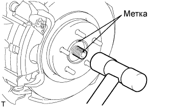
| 46. SEPARATE STEERING KNUCKLE WITH AXLE HUB LH |
Нанесите метки на приводной вал и ступицу колеса.
- ПРИМЕЧАНИЕ:
- Не наносите метки бородком.
С помощью молотка с пластмассовым покрытием отсоедините левую переднюю полуось в сборе.
- ПРИМЕЧАНИЕ:
- Будьте осторожны, чтобы не повредить чехол и ротор датчика частоты вращения.
- Не следует чрезмерно выталкивать приводной вал ведущего колеса из полуоси в сборе.
| 47. SEPARATE STEERING KNUCKLE WITH AXLE HUB RH |
- УКАЗАНИЕ:
- Perform the same procedure for the LH side.
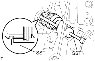
| 48. REMOVE FRONT DRIVE SHAFT ASSEMBLY LH |
С помощью SST снимите передний приводной вал.
- SST
- 09520-00031
09520-01010
- ПРИМЕЧАНИЕ:
- Будьте осторожны, чтобы не повредить сальник картера трансмиссии в блоке с главной передачей, чехол внутреннего шарнира и пылезащитный чехол приводного вала.
- Старайтесь не уронить приводной вал.
| 49. REMOVE FRONT DRIVE SHAFT ASSEMBLY RH |
- УКАЗАНИЕ:
- Порядок выполнения работ такой же, как для левой стороны.
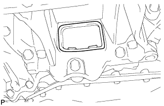
| 50. REMOVE FLYWHEEL HOUSING UNDER COVER (for Automatic Transaxle) |
Remove the flywheel housing under cover.
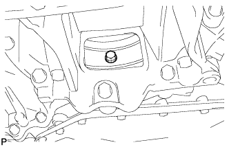
| 51. REMOVE DRIVE PLATE AND TORQUE CONVERTER CLUTCH SETTING BOLT (for Automatic Transaxle) |
Remove the 6 torque converter set bolts while holding the crankshaft pulley bolt with a wrench.
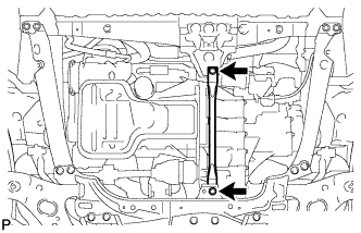
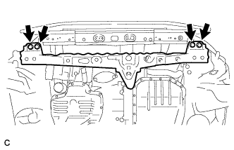
| 52. REMOVE ENGINE FRONT MOUNTING BRACKET REINFORCEMENT LOWER |
Выверните 2 болта и снимите нижнее усиление кронштейна передней опоры двигателя.
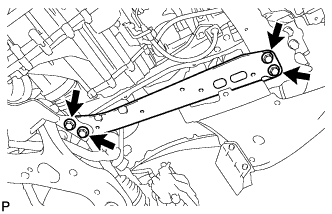
| 53. REMOVE FRONT SUSPENSION MEMBER REINFORCEMENT LH |
Выверните 4 болта и снимите левое усиление элемента передней подвески.
| 54. REMOVE FRONT SUSPENSION MEMBER REINFORCEMENT RH |
Выверните 4 болта и снимите правое усиление элемента передней подвески.
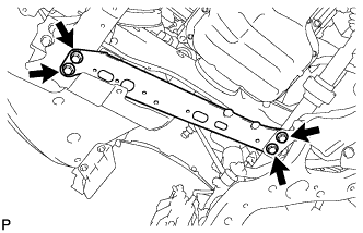
| 55. REMOVE FRONT SUSPENSION MEMBER REAR BRACE LH |
Выверните 3 болта и снимите левую заднюю скобу элемента передней подвески.
| 56. REMOVE FRONT SUSPENSION MEMBER REAR BRACE RH |
- УКАЗАНИЕ:
- Perform the same procedure for the LH side.
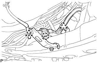
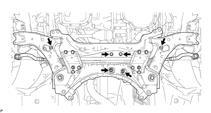
| 57. REMOVE FRONT SUSPENSION CROSSMEMBER SUB-ASSEMBLY |
Отцепите 2 зажима и захват, и отсоедините жгут проводов кислородного датчика от подрамника передней подвески в сборе.
Подоприте подрамник передней подвески телескопическим гидравлическим домкратом.
Выверните 4 болта, отверните 2 гайки и снимите подрамник передней подвески в сборе.
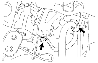
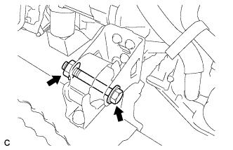
| 58. REMOVE FRONT CROSSMEMBER |
Remove the bolt and nut.
Remove the engine mounting insulator front from the engine mounting bracket front.
Remove the 4 bolts and front crossmember.
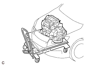
| 59. REMOVE ENGINE ASSEMBLY WITH TRANSAXLE |
Set the engine lifter.
- ПРИМЕЧАНИЕ:
- Place the engine on wooden blocks or equivalent so that the engine is level.
Remove the 2 bolts and nut, and separate the engine mounting insulator RH.
Remove the bolt and nut, and separate the engine mounting insulator LH.
Carefully remove the engine with transaxle from the vehicle.
| 60. REMOVE REAR ENGINE MOUNTING INSULATOR |
Remove the bolt and nut, and separate the rear engine mounting insulator.
| 61. INSTALL ENGINE HANGER |
Remove the air fuel ratio sensor bracket.
Install the 2 engine hangers with the 2 bolts.
- Момент затяжки:
- 43 Н*м{439 кгс*см, 32 фунт-сила-футов}
Part Name
| Part No.
|
No. 1 engine hanger
| 12281-37020
|
No. 2 engine hanger
| 12282-37010
|
Bolt
| 91552-81050
|
| 62. REMOVE FLYWHEEL HOUSING SIDE COVER |
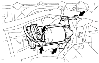
| 63. REMOVE STARTER ASSEMBLY |
Separate the 2 harness clamps.
Remove the bolt and wire harness bracket.
Remove the terminal cap.
Remove the nut and terminal 30.
Disconnect the connector.
Remove the 2 bolts and starter assembly.
| 64. REMOVE MANUAL TRANSAXLE ASSEMBLY (for Manual Transaxle) |
- УКАЗАНИЕ:
- See page Нажмите здесь for C66.
| 65. REMOVE AUTOMATIC TRANSAXLE ASSEMBLY (for Automatic Transaxle) |
- УКАЗАНИЕ:
- See page Нажмите здесь for U341E.
| 66. REMOVE CLUTCH COVER ASSEMBLY (for Manual Transaxle) |
- УКАЗАНИЕ:
- See page Нажмите здесь for C66.
| 67. REMOVE CLUTCH DISC ASSEMBLY (for Manual Transaxle) |
- УКАЗАНИЕ:
- See page Нажмите здесь for C66.
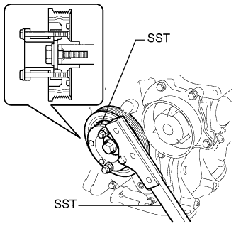
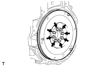
| 68. REMOVE FLYWHEEL SUB-ASSEMBLY (for Manual Transaxle) |
Using SST, hold the crankshaft.
- SST
- 09213-54015(91651-60855)
09330-00021
Remove the 8 bolts and the flywheel.
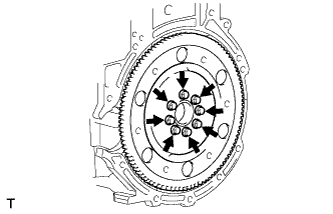
| 69. REMOVE DRIVE PLATE AND RING GEAR SUB-ASSEMBLY (for Automatic Transaxle) |
Using SST, hold the crankshaft.
- SST
- 09213-54015(91651-60855)
09330-00021
Remove the 8 bolts, rear spacer, drive plate and front spacer.
Set the engine on an engine stand.
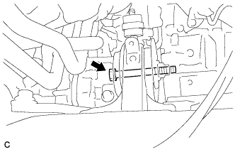
| 72. REMOVE FAN BELT ADJUSTING BAR |
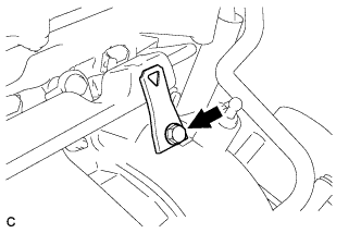
Remove the bolt and fan belt adjusting bar.
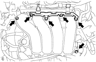
| 73. REMOVE INTAKE MANIFOLD |
Remove the wire harness clamp bracket.
Remove the 2 bolts and disconnect the air tube.
Disconnect the ventilation hose from the intake manifold.
Disconnect the 2 water by-pass hoses.
Remove the 4 bolts and 2 nuts, and remove the intake manifold and intake manifold stay.
Remove the gasket from the Intake manifold.
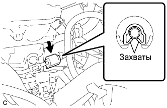
| 74. REMOVE FUEL TUBE SUB-ASSEMBLY |
Remove the No. 2 fuel pipe clamp (Type A).
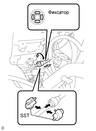
Remove the No. 2 fuel pipe clamp (Type B).
Using SST, disconnect the fuel tube sub-assembly (See page Нажмите здесь).
- SST
- 09268-21010
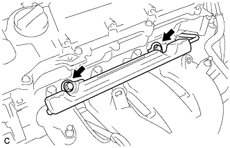
| 75. REMOVE FUEL DELIVERY PIPE SUB-ASSEMBLY |
Remove the bolt and remove the wire harness bracket.
Remove the 2 bolts.
Remove the bolt and the fuel delivery pipe sub-assembly.
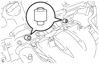
Remove the 2 No. 1 delivery pipe spacers.
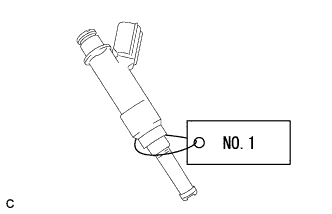
| 76. REMOVE FUEL INJECTOR ASSEMBLY |
Pull the 4 fuel injector assemblies out of the fuel delivery pipe sub-assembly.
For reinstallation, attach a tag or label to the injector shaft.
- ПРИМЕЧАНИЕ:
- Prevent entry of foreign objects by covering the fuel injector with plastic bags.
Remove the 4 injector vibration insulators.
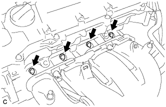
| 77. REMOVE IGNITION COIL ASSEMBLY |
Remove the 4 bolts and 4 ignition coils.
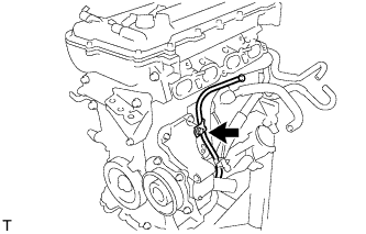
| 78. REMOVE OIL LEVEL GAUGE SUB-ASSEMBLY |
Remove the bolt and oil level gauge.
Remove the O-ring from the oil level gauge.
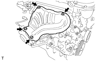
| 79. REMOVE NO. 1 EXHAUST MANIFOLD HEAT INSULATOR |
Remove the 4 bolts and exhaust manifold heat insulator.
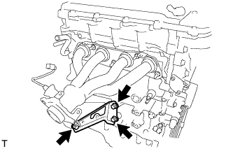
Remove the 3 bolts and exhaust manifold stay.
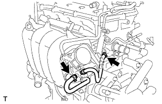
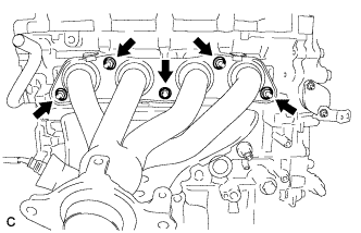
| 81. REMOVE EXHAUST MANIFOLD |
Remove the 5 bolts and exhaust manifold.
| 82. REMOVE VENTILATION HOSE |
Remove the ventilation hose.
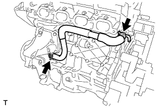
| 83. SEPARATE NO. 3 WATER BY-PASS HOSE |
Separate the No. 3 water by-pass hose from the water inlet housing.
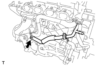
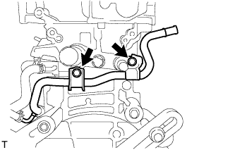
| 84. REMOVE NO. 1 WATER BY-PASS PIPE |
Remove the 2 bolts and No. 1 water by-pass pipe.
| 85. REMOVE WATER BY-PASS HOSE |
Remove the clamp and water by-pass hose.
| 86. REMOVE WATER INLET HOSE |
Remove the 2 clamps and water inlet hose.
Remove the 2 nuts and water inlet.
Remove the thermostat and gasket.
Remove the gasket from the thermostat.
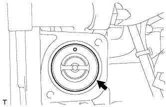
| 89. REMOVE RADIO SETTING CONDENSER |
Remove the bolt and radio setting condenser.
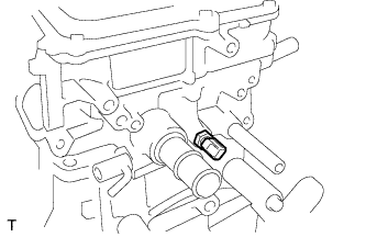
| 90. REMOVE ENGINE COOLANT TEMPERATURE SENSOR |
Using a 19 mm deep socket wrench, remove the sensor.
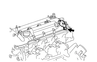
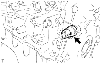
| 91. REMOVE KNOCK CONTROL SENSOR |
Disconnect the knock control sensor connector.
Remove the bolt and knock control sensor.
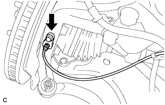
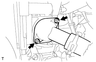
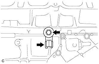
| 92. REMOVE ENGINE OIL PRESSURE SWITCH ASSEMBLY |
Using a 24 mm deep socket wrench, remove the sensor.