Двигатель. COROLLA, AURIS. ZZE150 ZRE151,152 NDE150
DESCRIPTION
INSPECTION PROCEDURE
PERFORM ACTIVE TEST USING INTELLIGENT TESTER (CONTROL THE COOLING FAN)
INSPECT COOLING FAN ECU
CHECK HARNESS AND CONNECTOR (ECM - COOLING FAN ECU)
INSPECT COOLING FAN MOTOR
CHECK COOLING FAN ECU (POWER SOURCE)
CHECK HARNESS AND CONNECTOR (COOLING FAN ECU - BODY GROUND)
INSPECT FAN NO. 1 RELAY
INSPECT FUSIBLE LINK BLOCK (RAD FAN FUSE)
INSPECT FUSE (ECU-IG NO. 1)
CHECK HARNESS AND CONNECTOR (COOLING FAN ECU - FAN NO. 1 RELAY)
CHECK HARNESS AND CONNECTOR (FAN NO. 1 RELAY - BODY GROUND)
CHECK HARNESS AND CONNECTOR (FAN NO. 1 RELAY - ECU-IG NO. 1 FUSE)
CHECK HARNESS AND CONNECTOR (FAN NO. 1 RELAY - RDI FAN FUSE)
ВЕНТИЛЯТОР СИСТЕМЫ ОХЛАЖДЕНИЯ - Цепь вентилятора системы охлаждения |
DESCRIPTION
The ECM calculates an appropriate cooling fan speed based on the engine coolant temperature, air conditioning switch condition, refrigerant pressure, engine speed, and vehicle speed and sends the signals to the cooling fan ECU to regulate the cooling fan. The cooling fan ECU controls the cooling fan speed based on the duty ratio signal sent from the ECM. By basing its control on the operating conditions, the ECM can control the fan speed optimally using the cooling fan ECU, achieving both high cooling performance and quietness. The cooling fan speed is determined based on engine coolant temperature, air conditioner operating conditions, engine speed, and vehicle speed.
INSPECTION PROCEDURE
| 1.PERFORM ACTIVE TEST USING INTELLIGENT TESTER (CONTROL THE COOLING FAN) |
Connect the intelligent tester to the DLC3.
Turn the ignition switch on (IG).
Enter the following menus: Powertrain / Engine and ECT / Active Test / Control the Cooling Fan.
Check the operation of the cooling fan while operating it using the intelligent tester.
- OK:
- The cooling fan rotates.
| 2.INSPECT COOLING FAN ECU |
Disconnect the ECM connector.
Turn the ignition switch on (IG).
Check the operation of the cooling fan.
- OK:
- The cooling fan rotates.
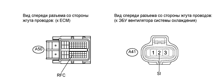
| 3.CHECK HARNESS AND CONNECTOR (ECM - COOLING FAN ECU) |
Disconnect the cooling fan ECU connector.
Disconnect the ECM connector.
Measure the resistance according to the value(s) in the table below.
- Standard resistance:
Tester Connection
| Condition
| Specified Condition
|
A50-43 (RFC) - A41-2 (SI)
| Always
| Below 1 Ω
|
| | REPAIR OR REPLACE HARNESS OR CONNECTOR (ECM - COOLING FAN ECU) |
|
|
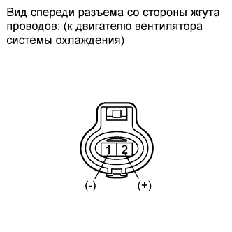
| 4.INSPECT COOLING FAN MOTOR |
Disconnect the cooling fan ECU connector.
Connect the battery positive terminal to terminal 2 of the cooling fan connector, and connect the battery negative terminal to terminal 1 of the cooling fan connector.
Connect the cooling fan motor.
- OK:
- The cooling fan rotates.
| | REPLACE COOLING FAN MOTOR |
|
|
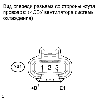
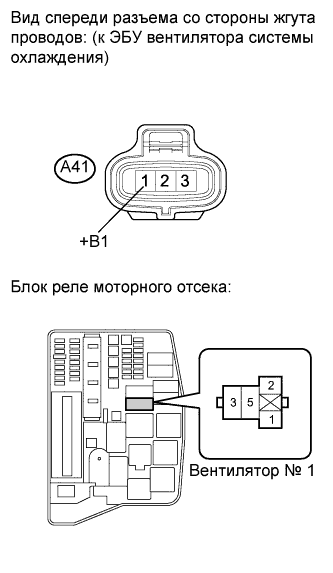
| 5.CHECK COOLING FAN ECU (POWER SOURCE) |
Disconnect the cooling fan ECU connector.
Turn the ignition switch on (IG).
Measure the voltage according to the value(s) in the table below.
- Standard voltage:
Tester Connection
| Switch Condition
| Specified Condition
|
A41-1 (+B1) - A41-3 (E1)
| Ignition switch on (IG)
| 9 to 14 V
|
| 6.CHECK HARNESS AND CONNECTOR (COOLING FAN ECU - BODY GROUND) |
Measure the resistance according to the value(s) in the table below.
- Standard resistance:
Tester Connection
| Condition
| Specified Condition
|
A41-3 (E1) - Body ground
| Always
| Below 1 Ω
|
| | REPAIR OR REPLACE HARNESS OR CONNECTOR (COOLING FAN ECU - BODY GROUND) |
|
|
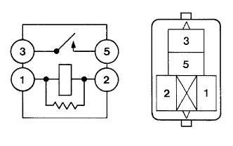
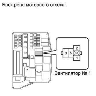
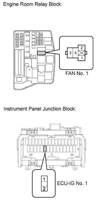
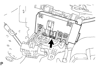
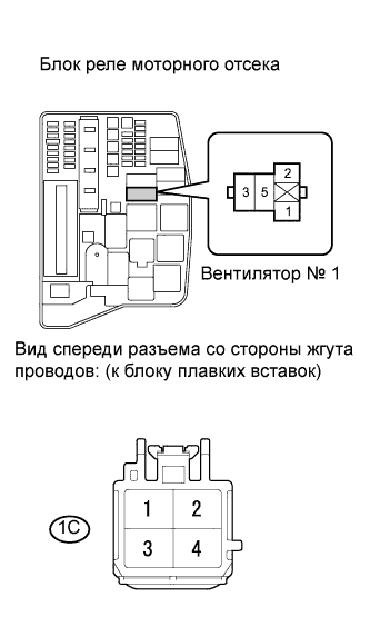
| 7.INSPECT FAN NO. 1 RELAY |
Remove the FAN No. 1 relay from the engine room relay block.
Measure the resistance according to the value(s) in the table below.
- Standard resistance:
Tester Connection
| Condition
| Specified Condition
|
3 - 5
| Normal
| 10 kΩ or higher
|
3 - 5
| Apply battery voltage between terminals 1 and 2
| Below 1 Ω
|
| 8.INSPECT FUSIBLE LINK BLOCK (RAD FAN FUSE) |
Check the RAD FAN fuse.
| | REPLACE FUSIBLE LINK BLOCK |
|
|
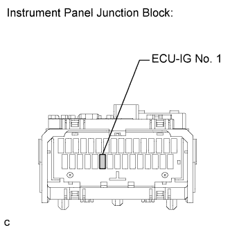
| 9.INSPECT FUSE (ECU-IG NO. 1) |
Remove the ECU-IG No. 1 fuse from the instrument panel junction block.
Measure the resistance according to the value(s) in the table below.
- Standard resistance:
Tester Connection
| Condition
| Specified Condition
|
ECU-IG No. 1 fuse
| Always
| Below 1 Ω
|
| | REPLACE FUSE (ECU-IG NO. 1 FUSE) |
|
|
| 10.CHECK HARNESS AND CONNECTOR (COOLING FAN ECU - FAN NO. 1 RELAY) |
Disconnect the cooling fan ECU connector.
Remove the FAN No. 1 relay from the engine room relay block.
Measure the resistance according to the value(s) in the table below.
- Standard resistance:
Tester Connection
| Condition
| Specified Condition
|
A41-1 (+B1) - 5 (FAN No.1 relay)
| Always
| Below 1 Ω
|
| | REPAIR OR REPLACE HARNESS OR CONNECTOR (COOLING FAN ECU - FAN NO. 1 RELAY) |
|
|
| 11.CHECK HARNESS AND CONNECTOR (FAN NO. 1 RELAY - BODY GROUND) |
Remove the FAN No. 1 relay from the engine room relay block.
Measure the resistance according to the value(s) in the table below.
- Standard resistance:
Tester Connection
| Condition
| Specified Condition
|
2 (FAN No.1 relay) - Body ground
| Always
| Below 1 Ω
|
| | REPAIR OR REPLACE HARNESS OR CONNECTOR (FAN NO. 1 RELAY - BODY GROUND) |
|
|
| 12.CHECK HARNESS AND CONNECTOR (FAN NO. 1 RELAY - ECU-IG NO. 1 FUSE) |
Remove the ECU-IG No. 1 fuse from the instrument panel junction block.
Remove the FAN No. 1 relay from the engine room relay block.
Measure the resistance according to the value(s) in the table below.
- Standard resistance:
Tester Connection
| Condition
| Specified Condition
|
2 (ECU-IG No. 1 fuse) - 1 (FAN No.1 relay)
| Always
| Below 1 Ω
|
| | REPAIR OR REPLACE HARNESS OR CONNECTOR (FAN NO. 1 RELAY - ECU-IG NO. 1 FUSE) |
|
|
| 13.CHECK HARNESS AND CONNECTOR (FAN NO. 1 RELAY - RDI FAN FUSE) |
Remove the fusible link block assembly.
Disconnect the connector.
Measure the resistance according to the value(s) in the table below.
- Standard resistance:
Tester Connection
| Condition
| Specified Condition
|
3 (FAN No. 1 relay) - 1C-2 (Fusible link block)
| Always
| Below 1 Ω
|
| | REPAIR OR REPLACE HARNESS OR CONNECTOR (FAN NO. 1 RELAY - RDI FAN FUSE) |
|
|
| OK |
|
|
|
| REPAIR OR REPLACE HARNESS OR CONNECTOR (BATTERY - RDI FAN FUSE) |
|