Масляный Насос Снятие. Corolla Auris
Двигатель. COROLLA, AURIS. ZZE150 ZRE151,152 NDE150
REMOVE ENGINE ASSEMBLY WITH TRANSAXLE
REMOVE REAR ENGINE MOUNTING INSULATOR
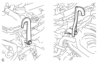
REMOVE ENGINE HANGER
REMOVE FLYWHEEL HOUSING SIDE COVER
REMOVE STARTER ASSEMBLY
REMOVE MANUAL TRANSAXLE ASSEMBLY (for Manual Transaxle)
REMOVE AUTOMATIC TRANSAXLE ASSEMBLY (for Automatic Transaxle)
REMOVE CLUTCH COVER ASSEMBLY (for Manual Transaxle)
REMOVE CLUTCH DISC ASSEMBLY (for Manual Transaxle)
REMOVE FLYWHEEL SUB-ASSEMBLY (for Manual Transaxle)
REMOVE DRIVE PLATE AND RING GEAR SUB-ASSEMBLY (for Automatic Transaxle)
REMOVE ENGINE WIRE
INSTALL ENGINE STAND
REMOVE INTAKE MANIFOLD
REMOVE FUEL TUBE SUB-ASSEMBLY
REMOVE FUEL DELIVERY PIPE SUB-ASSEMBLY
REMOVE FUEL INJECTOR ASSEMBLY
REMOVE IGNITION COIL ASSEMBLY
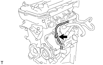
REMOVE OIL LEVEL GAGE SUB-ASSEMBLY
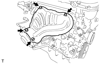
REMOVE NO. 1 EXHAUST MANIFOLD HEAT INSULATOR
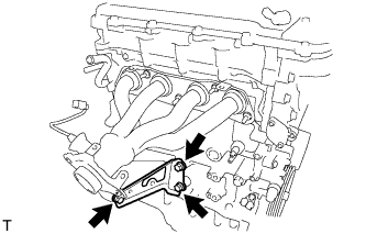
REMOVE MANIFOLD STAY
REMOVE EXHAUST MANIFOLD
REMOVE VENTILATION HOSE
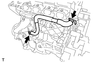
REMOVE NO. 3 WATER BY-PASS HOSE
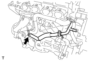
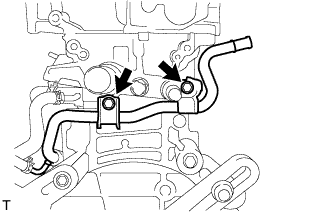
REMOVE NO. 1 WATER BY-PASS PIPE
REMOVE WATER BY-PASS HOSE
REMOVE WATER INLET HOSE
REMOVE WATER INLET
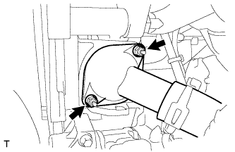
REMOVE THERMOSTAT
REMOVE RADIO SETTING CONDENSER
REMOVE CYLINDER HEAD COVER SUB-ASSEMBLY
REMOVE CYLINDER HEAD COVER GASKET
SET NO. 1 CYLINDER TO TDC / COMPRESSION
REMOVE CRANKSHAFT PULLEY
REMOVE NO. 1 CHAIN TENSIONER ASSEMBLY
REMOVE TIMING CHAIN COVER SUB-ASSEMBLY
REMOVE CHAIN TENSIONER SLIPPER
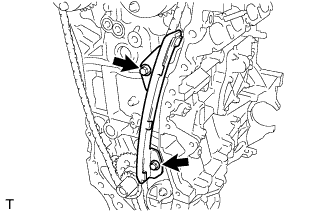
REMOVE NO. 1 CHAIN VIBRATION DAMPER
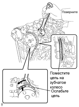
REMOVE CHAIN SUB-ASSEMBLY
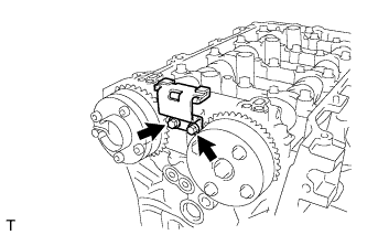
REMOVE NO. 2 CHAIN VIBRATION DAMPER
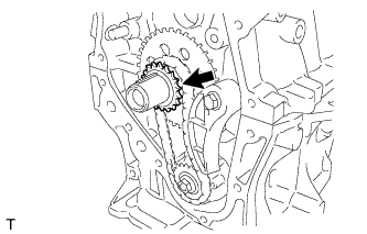
REMOVE CRANKSHAFT TIMING SPROCKET
REMOVE NO. 2 CHAIN SUB-ASSEMBLY
REMOVE NO. 1 CRANKSHAFT POSITION SENSOR PLATE
REMOVE NO. 2 OIL PAN SUB-ASSEMBLY
REMOVE OIL PUMP ASSEMBLY
| 1. REMOVE ENGINE ASSEMBLY WITH TRANSAXLE |
(See page Нажмите здесь).
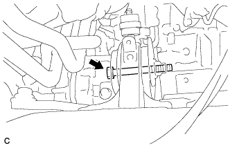
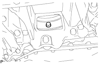
| 2. REMOVE REAR ENGINE MOUNTING INSULATOR |
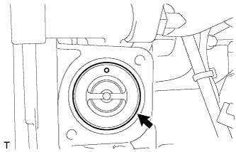
Remove the bolt and nut, and separate the rear engine mounting insulator.
Remove the air fuel ratio sensor bracket.
Install the 2 engine hangers with the 2 bolts.
- Момент затяжки:
- 43 Н*м{439 кгс*см, 32 фунт-сила-футов}
Part Name
| Part No.
|
No. 1 engine hanger
| 12281-37020
|
No. 2 engine hanger
| 12282-37010
|
Bolt
| 91552-81050
|
| 4. REMOVE FLYWHEEL HOUSING SIDE COVER |
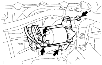
| 5. REMOVE STARTER ASSEMBLY |
Separate the 2 harness clamps.
Remove the bolt and wire harness bracket.
Remove the terminal cap.
Remove the nut and terminal 30.
Disconnect the connector.
Remove the 2 bolts and starter assembly.
| 6. REMOVE MANUAL TRANSAXLE ASSEMBLY (for Manual Transaxle) |
- УКАЗАНИЕ:
- See page Нажмите здесь for C66
| 7. REMOVE AUTOMATIC TRANSAXLE ASSEMBLY (for Automatic Transaxle) |
- УКАЗАНИЕ:
- See page Нажмите здесь for U341E
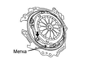
| 8. REMOVE CLUTCH COVER ASSEMBLY (for Manual Transaxle) |
Совместите метки на кожухе сцепления в сборе и маховике.
Ослабьте все установочные болты, отворачивая их за одну операцию на один оборот, пока не ослабнет натяжение пружины.
Выверните установочные болты и снимите кожух сцепления.
- ПРИМЕЧАНИЕ:
- Будьте осторожны, не уроните ведомый диск сцепления.
| 9. REMOVE CLUTCH DISC ASSEMBLY (for Manual Transaxle) |
- ПРИМЕЧАНИЕ:
- Не допускайте попадания масла и посторонних материалов на вкладыш ведомого диска сцепления в сборе, нажимной диск сцепления и поверхность маховика в сборе.
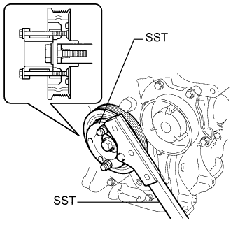
| 10. REMOVE FLYWHEEL SUB-ASSEMBLY (for Manual Transaxle) |
Using SST, hold the crankshaft.
- SST
- 09213-54015(91651-60855)
09330-00021
Remove the 8 bolts and the flywheel.
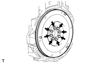
| 11. REMOVE DRIVE PLATE AND RING GEAR SUB-ASSEMBLY (for Automatic Transaxle) |
Remove the 6 torque converter set bolts while holding the crankshaft pulley bolt with a wrench.
Set the engine on an engine stand.
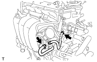
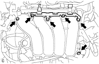
| 14. REMOVE INTAKE MANIFOLD |
Remove the wire harness clamp bracket.
Remove the 2 bolts and disconnect the air tube.
Disconnect the ventilation hose from the intake manifold.
Disconnect the 2 water by-pass hoses.
Remove the 4 bolts and 2 nuts, and remove the intake manifold and intake manifold stay.
Remove the gasket from the Intake manifold.
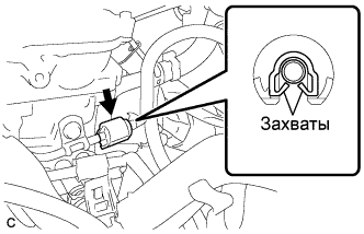
| 15. REMOVE FUEL TUBE SUB-ASSEMBLY |
Remove the No. 2 fuel pipe clamp (Type A).
Remove the No. 2 fuel pipe clamp (Type B).
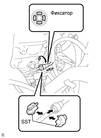
Using SST, disconnect the fuel tube sub-assembly (See page Нажмите здесь).
- SST
- 09268-21010
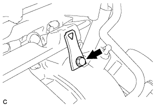
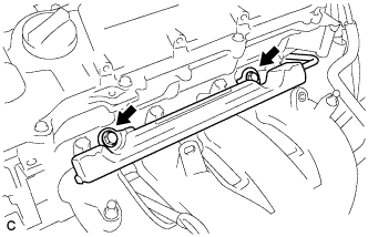
| 16. REMOVE FUEL DELIVERY PIPE SUB-ASSEMBLY |
Remove the bolt and remove the wire harness bracket.
Remove the 2 bolts.
Remove the bolt and the fuel delivery pipe sub-assembly.
Remove the 2 No. 1 delivery pipe spacers.
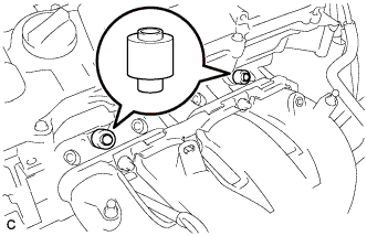
| 17. REMOVE FUEL INJECTOR ASSEMBLY |
Pull the 4 fuel injector assemblies out of the fuel delivery pipe sub-assembly.
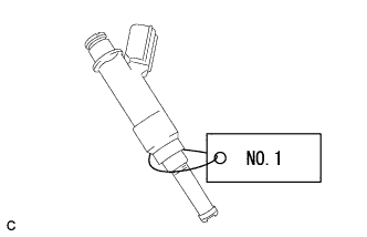
For reinstallation, attach a tag or label to the injector shaft.
- ПРИМЕЧАНИЕ:
- Prevent entry of foreign objects by covering the fuel injector with plastic bags.
Remove the 4 injector vibration insulators.
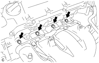
| 18. REMOVE IGNITION COIL ASSEMBLY |
Remove the 4 bolts and 4 ignition coils.
| 19. REMOVE OIL LEVEL GAGE SUB-ASSEMBLY |
Remove the bolt and oil level gauge.
Remove the O-ring from the oil level gauge.
| 20. REMOVE NO. 1 EXHAUST MANIFOLD HEAT INSULATOR |
Remove the 4 bolts and exhaust manifold heat insulator.
Remove the 3 bolts and exhaust manifold stay.
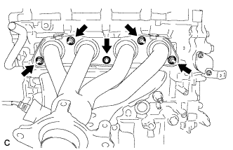
| 22. REMOVE EXHAUST MANIFOLD |
Remove the 5 bolts and exhaust manifold.
| 23. REMOVE VENTILATION HOSE |
Remove the ventilation hose.
| 24. REMOVE NO. 3 WATER BY-PASS HOSE |
Separate the No. 3 water by-pass hose from the water inlet housing.
| 25. REMOVE NO. 1 WATER BY-PASS PIPE |
Remove the 2 bolts and No. 1 water by-pass pipe.
| 26. REMOVE WATER BY-PASS HOSE |
Remove the clamp and water by-pass hose.
| 27. REMOVE WATER INLET HOSE |
Remove the 2 clamps and water inlet hose.
Remove the 2 nuts and water inlet.
Remove the thermostat and gasket.
Remove the gasket from the thermostat.
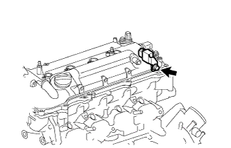
| 30. REMOVE RADIO SETTING CONDENSER |
Remove the bolt and radio setting condenser.
| 31. REMOVE CYLINDER HEAD COVER SUB-ASSEMBLY |
Remove the 13 bolts, seal washer and cylinder head cover.
Remove the 3 gaskets from the camshaft bearing cap.
- ПРИМЕЧАНИЕ:
- Be careful not to drop any of the gaskets into the engine when removing the cylinder head cover because gaskets may stick to the cylinder head cover.
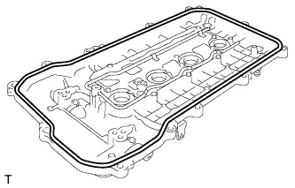
| 32. REMOVE CYLINDER HEAD COVER GASKET |
Remove the cylinder head cover gasket.
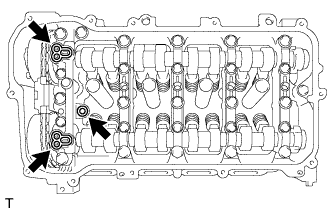
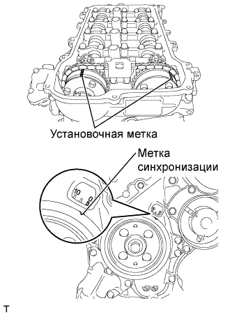
| 33. SET NO. 1 CYLINDER TO TDC / COMPRESSION |
Turn the crankshaft pulley until its groove and the timing mark "0" of the timing chain cover are aligned.
Check that each timing mark of the camshaft timing gear and sprocket are aligned with each timing mark located on the No. 1 and No. 2 bearing caps as shown in the illustration. If not, turn the crankshaft by 1 revolution (360°) to align the timing marks as above.
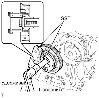
| 34. REMOVE CRANKSHAFT PULLEY |
Using SST, hold the pulley in place and loosen the pulley bolt.
- SST
- 09213-54015(91651-60855)
09330-00021
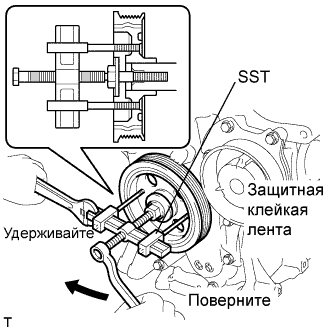
Using SST, remove the crankshaft pulley and pulley bolt.
- SST
- 09950-50013(09951-05010,09952-05010,09953-05020,09954-05021)
- УКАЗАНИЕ:
- If necessary, remove the pulley and pulley bolt using SST.
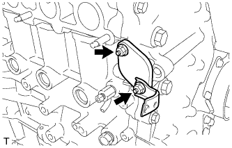
| 35. REMOVE NO. 1 CHAIN TENSIONER ASSEMBLY |
Remove the 2 nuts, bracket, tensioner and gasket.
- ПРИМЕЧАНИЕ:
- Do not turn the crankshaft without the chain tensioner.
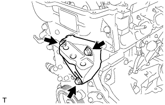
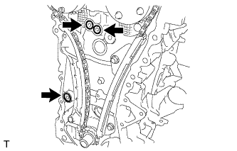
| 36. REMOVE TIMING CHAIN COVER SUB-ASSEMBLY |
Remove the 3 bolts and engine mounting bracket.
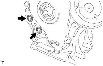
Remove the 4 bolts and oil filter bracket.
Remove the 2 O-rings.
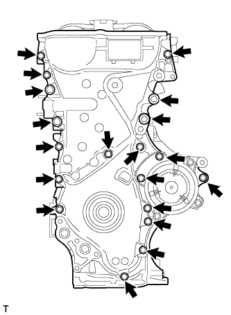
Remove the 19 bolts.
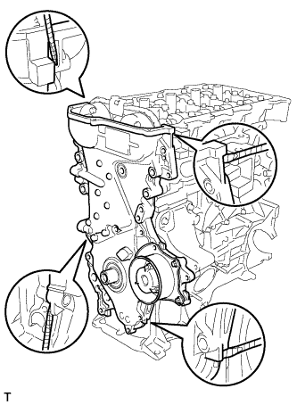
Remove the timing chain cover by prying between the timing chain cover and cylinder head or cylinder block with a screwdriver.
- ПРИМЕЧАНИЕ:
- Be careful not to damage the contact surfaces of the timing chain cover, cylinder block, and cylinder head.
- УКАЗАНИЕ:
- Tape the screwdriver tip before use.
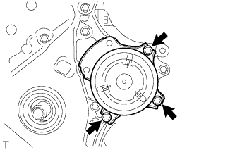
Remove the 3 O-rings.
Remove the 3 bolts and water pump.
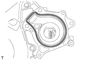
Remove the gasket.
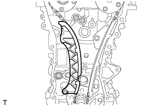
| 37. REMOVE CHAIN TENSIONER SLIPPER |
Remove the chain tensioner slipper.
| 38. REMOVE NO. 1 CHAIN VIBRATION DAMPER |
Remove the 2 bolts and No. 1 chain vibration damper.
| 39. REMOVE CHAIN SUB-ASSEMBLY |
Hold the hexagonal portion of the camshaft with a wrench and turn the camshaft timing gear assembly counterclockwise to loosen the chain between the camshaft timing gears.
With the chain loosened, release the chain from the camshaft timing gear assembly and place it on the camshaft timing gear assembly.
- УКАЗАНИЕ:
- Be sure to release the chain from the sprocket completely.
Turn the camshaft clockwise to return it to the original position and remove the chain.
| 40. REMOVE NO. 2 CHAIN VIBRATION DAMPER |
Remove the 2 bolts and No. 2 chain vibration damper.
| 41. REMOVE CRANKSHAFT TIMING SPROCKET |
Remove the crankshaft timing sprocket.
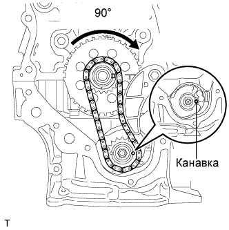
| 42. REMOVE NO. 2 CHAIN SUB-ASSEMBLY |
Temporarily tighten the crank pulley bolt.
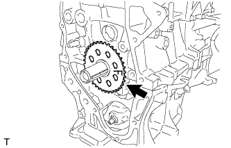
Turn the crankshaft 90° clockwise to align the adjusting hole of the oil pump drive shaft sprocket with the groove of the oil pump.
- ПРИМЕЧАНИЕ:
- Do not rotate the crankshaft more than 90°. If the crankshaft is rotated too much without the timing chain installed, the valves may hit the pistons and cause damage.
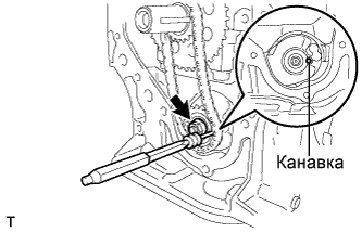
Remove the crank pulley bolt.
Insert a 3 mm diameter bar into the adjusting hole of the oil pump drive shaft sprocket to lock the gear in position, and then remove the nut.
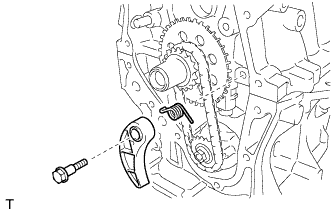
Remove the bolt, chain tensioner plate, and spring.
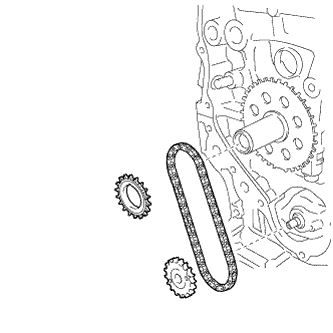
Remove the crankshaft timing sprocket, oil pump drive shaft gear, and No. 2 chain sub-assembly.
| 43. REMOVE NO. 1 CRANKSHAFT POSITION SENSOR PLATE |
Remove the No. 1 crankshaft position sensor plate.
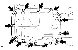
| 44. REMOVE NO. 2 OIL PAN SUB-ASSEMBLY |
Remove the 10 bolts and 2 nuts.
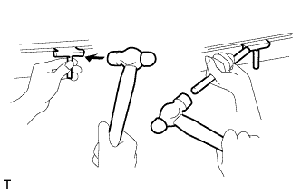
Insert the blade of SST between the crankcase and oil pan. Cut through the sealer and remove the oil pan.
- SST
- 09032-00100
- ПРИМЕЧАНИЕ:
- Be careful not to damage the contact surfaces of the crankcase, chain cover, and oil pan.
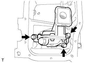
| 45. REMOVE OIL PUMP ASSEMBLY |
Remove the 3 bolts and oil pump.