Прокладка Головки Блока Цилиндров Снятие. Corolla Auris
Двигатель. COROLLA, AURIS. ZZE150 ZRE151,152 NDE150
REMOVE ENGINE ASSEMBLY WITH TRANSAXLE
REMOVE REAR ENGINE MOUNTING INSULATOR
INSTALL ENGINE HANGER
REMOVE FLYWHEEL HOUSING SIDE COVER
REMOVE STARTER ASSEMBLY
REMOVE MANUAL TRANSAXLE ASSEMBLY (for Manual Transaxle)
REMOVE AUTOMATIC TRANSAXLE ASSEMBLY (for Automatic Transaxle)
REMOVE CLUTCH COVER ASSEMBLY (for Manual Transaxle)
REMOVE CLUTCH DISC ASSEMBLY (for Manual Transaxle)
REMOVE FLYWHEEL SUB-ASSEMBLY (for Manual Transaxle)
REMOVE DRIVE PLATE AND RING GEAR SUB-ASSEMBLY (for Automatic Transaxle)
REMOVE ENGINE WIRE
INSTALL ENGINE STAND
REMOVE INTAKE MANIFOLD
REMOVE FUEL TUBE SUB-ASSEMBLY
REMOVE FUEL DELIVERY PIPE SUB-ASSEMBLY
REMOVE FUEL INJECTOR ASSEMBLY
REMOVE IGNITION COIL ASSEMBLY
REMOVE OIL LEVEL GAUGE SUB-ASSEMBLY
REMOVE NO. 1 EXHAUST MANIFOLD HEAT INSULATOR
REMOVE MANIFOLD STAY
REMOVE EXHAUST MANIFOLD
REMOVE VENTILATION HOSE
REMOVE NO. 3 WATER BY-PASS HOSE
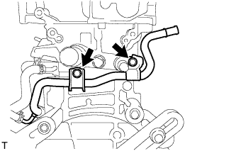
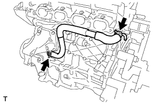
REMOVE NO. 1 WATER BY-PASS PIPE
REMOVE WATER BY-PASS HOSE
REMOVE WATER INLET HOSE
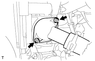
REMOVE WATER INLET
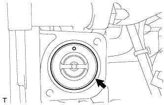
REMOVE THERMOSTAT
REMOVE RADIO SETTING CONDENSER
REMOVE CYLINDER HEAD COVER SUB-ASSEMBLY
REMOVE CYLINDER HEAD COVER GASKET
SET NO. 1 CYLINDER TO TDC/COMPRESSION
REMOVE CRANKSHAFT PULLEY
REMOVE NO. 1 CHAIN TENSIONER ASSEMBLY
REMOVE TIMING CHAIN COVER SUB-ASSEMBLY
REMOVE CHAIN TENSIONER SLIPPER
REMOVE NO. 1 CHAIN VIBRATION DAMPER
REMOVE CHAIN SUB-ASSEMBLY
REMOVE NO. 2 CHAIN VIBRATION DAMPER
REMOVE CAMSHAFT TIMING EXHAUST GEAR ASSEMBLY
REMOVE CAMSHAFT BEARING CAP
REMOVE NO. 1 VALVE ROCKER ARM SUB-ASSEMBLY
REMOVE VALVE LASH ADJUSTER ASSEMBLY
REMOVE CAMSHAFT TIMING GEAR ASSEMBLY
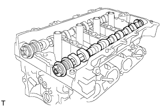
REMOVE CAMSHAFT
REMOVE NO. 2 CAMSHAFT
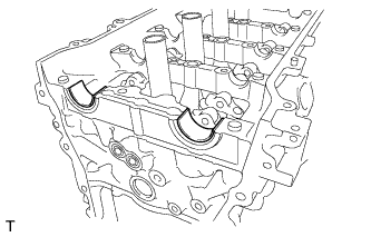
REMOVE NO. 1 CAMSHAFT BEARING
REMOVE NO. 2 CAMSHAFT BEARING
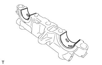
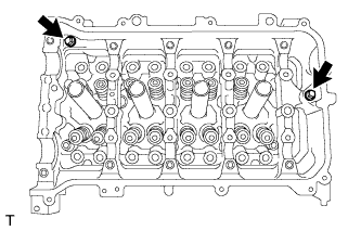
REMOVE CAMSHAFT HOUSING SUB-ASSEMBLY
REMOVE CYLINDER HEAD SUB-ASSEMBLY
REMOVE CYLINDER HEAD GASKET
INSPECT NO. 1 VALVE ROCKER ARM SUB-ASSEMBLY
INSPECT VALVE LASH ADJUSTER ASSEMBLY
INSPECT CYLINDER HEAD SET BOLT
Прокладка Головки Блока Цилиндров -- Снятие |
| 1. REMOVE ENGINE ASSEMBLY WITH TRANSAXLE |
- УКАЗАНИЕ:
- See page Нажмите здесь.
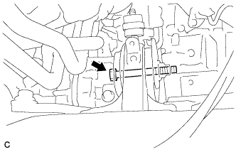
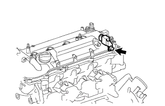
| 2. REMOVE REAR ENGINE MOUNTING INSULATOR |
Remove the bolt and nut, and separate the rear engine mounting insulator.
Remove the air fuel ratio sensor bracket.
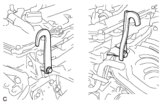
Install the 2 engine hangers with the 2 bolts.
- Момент затяжки:
- 43 Н*м{439 кгс*см, 32 фунт-сила-футов}
Part Name
| Part No.
|
No. 1 engine hanger
| 12281-37020
|
No. 2 engine hanger
| 12282-37010
|
Bolt
| 91552-81050
|
| 4. REMOVE FLYWHEEL HOUSING SIDE COVER |
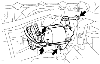
| 5. REMOVE STARTER ASSEMBLY |
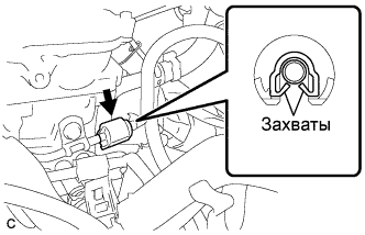
Separate the 2 harness clamps.
Remove the bolt and wire harness bracket.
Remove the terminal cap.
Remove the nut and terminal 30.
Disconnect the connector.
Remove the 2 bolts and starter assembly.
| 6. REMOVE MANUAL TRANSAXLE ASSEMBLY (for Manual Transaxle) |
- УКАЗАНИЕ:
- See page Нажмите здесь for C66.
| 7. REMOVE AUTOMATIC TRANSAXLE ASSEMBLY (for Automatic Transaxle) |
- УКАЗАНИЕ:
- See page Нажмите здесь for U341E.
| 8. REMOVE CLUTCH COVER ASSEMBLY (for Manual Transaxle) |
- УКАЗАНИЕ:
- See page Нажмите здесь for C66.
| 9. REMOVE CLUTCH DISC ASSEMBLY (for Manual Transaxle) |
- УКАЗАНИЕ:
- See page Нажмите здесь for C66.
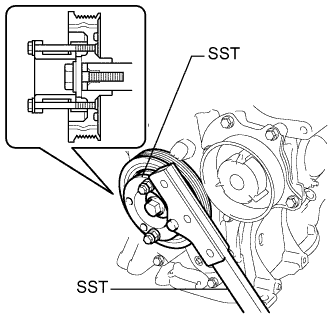
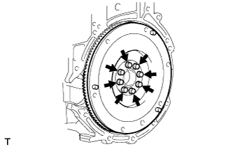
| 10. REMOVE FLYWHEEL SUB-ASSEMBLY (for Manual Transaxle) |
Using SST, hold the crankshaft.
- SST
- 09213-54015(91651-60855)
09330-00021
Remove the 8 bolts and the flywheel.
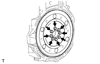
| 11. REMOVE DRIVE PLATE AND RING GEAR SUB-ASSEMBLY (for Automatic Transaxle) |
Using SST, hold the crankshaft.
- SST
- 09213-54015(91651-60855)
09330-00021
Remove the 8 bolts, rear spacer, drive plate and front spacer.
Set the engine on an engine stand.
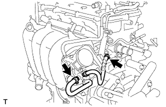
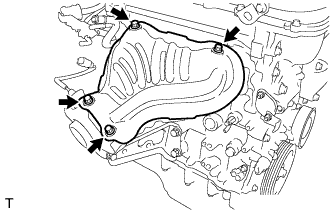
| 14. REMOVE INTAKE MANIFOLD |
Remove the wire harness clamp bracket.
Remove the 2 bolts and disconnect the air tube.
Disconnect the ventilation hose from the intake manifold.
Disconnect the 2 water by-pass hoses.
Remove the 4 bolts and 2 nuts, and remove the intake manifold and intake manifold stay.
Remove the gasket from the Intake manifold.
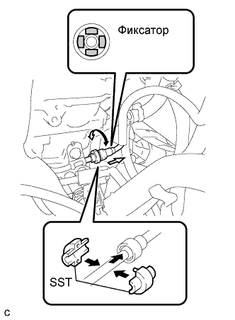
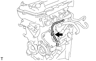
| 15. REMOVE FUEL TUBE SUB-ASSEMBLY |
Remove the No. 2 fuel pipe clamp (Type A).
Remove the No. 2 fuel pipe clamp (Type B).
Using SST, disconnect the fuel tube sub-assembly (See page Нажмите здесь).
- SST
- 09268-21010
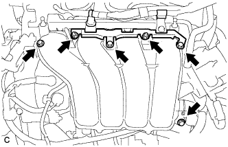
| 16. REMOVE FUEL DELIVERY PIPE SUB-ASSEMBLY |
Remove the bolt and remove the wire harness bracket.
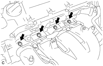
Remove the 2 bolts.
Remove the bolt and the fuel delivery pipe sub-assembly.
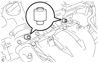
Remove the 2 No. 1 delivery pipe spacers.
| 17. REMOVE FUEL INJECTOR ASSEMBLY |
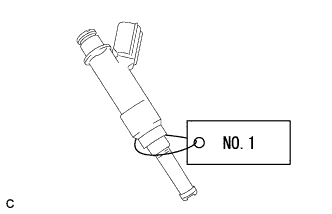
Pull the 4 fuel injector assemblies out of the fuel delivery pipe sub-assembly.
For reinstallation, attach a tag or label to the injector shaft.
- ПРИМЕЧАНИЕ:
- Prevent entry of foreign objects by covering the fuel injector with plastic bags.
Remove the 4 injector vibration insulators.
| 18. REMOVE IGNITION COIL ASSEMBLY |
Remove the 4 bolts and 4 ignition coils.
| 19. REMOVE OIL LEVEL GAUGE SUB-ASSEMBLY |
Remove the bolt and oil level gauge.
Remove the O-ring from the oil level gauge.
| 20. REMOVE NO. 1 EXHAUST MANIFOLD HEAT INSULATOR |
Remove the 4 bolts and exhaust manifold heat insulator.
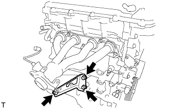
Remove the 3 bolts and exhaust manifold stay.
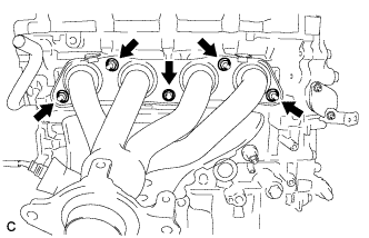
| 22. REMOVE EXHAUST MANIFOLD |
Remove the 5 bolts and exhaust manifold.
| 23. REMOVE VENTILATION HOSE |
Remove the ventilation hose.
| 24. REMOVE NO. 3 WATER BY-PASS HOSE |
Separate the No. 3 water by-pass hose from the water inlet housing.
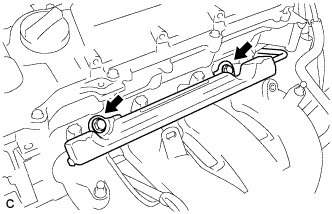
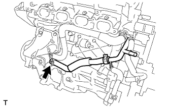
| 25. REMOVE NO. 1 WATER BY-PASS PIPE |
Remove the 2 bolts and No. 1 water by-pass pipe.
| 26. REMOVE WATER BY-PASS HOSE |
Remove the clamp and water by-pass hose.
| 27. REMOVE WATER INLET HOSE |
Remove the 2 clamps and water inlet hose.
Remove the 2 nuts and water inlet.
Remove the thermostat and gasket.
Remove the gasket from the thermostat.
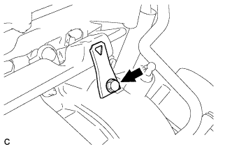
| 30. REMOVE RADIO SETTING CONDENSER |
Remove the bolt and radio setting condenser.
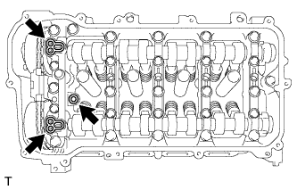
| 31. REMOVE CYLINDER HEAD COVER SUB-ASSEMBLY |
Remove the 13 bolts, seal washer and cylinder head cover.
Remove the 3 gaskets from the camshaft bearing cap.
- ПРИМЕЧАНИЕ:
- Be careful not to drop any of the gaskets into the engine when removing the cylinder head cover because gaskets may stick to the cylinder head cover.
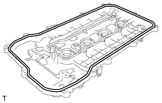
| 32. REMOVE CYLINDER HEAD COVER GASKET |
Remove the cylinder head cover gasket.
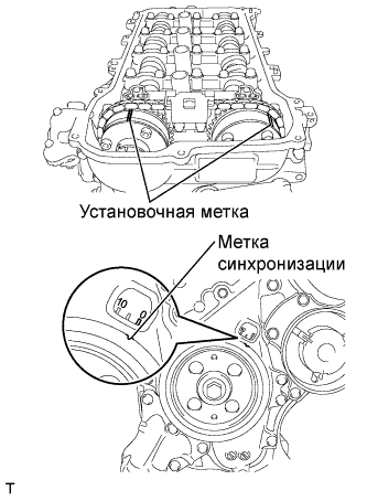
| 33. SET NO. 1 CYLINDER TO TDC/COMPRESSION |
Turn the crankshaft pulley until its groove and the timing mark "0" of the timing chain cover are aligned.
Check that each timing mark of the camshaft timing gear and sprocket are aligned with each timing mark located on the No. 1 and No. 2 bearing caps as shown in the illustration. If not, turn the crankshaft by 1 revolution (360°) to align the timing marks as above.
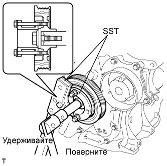
| 34. REMOVE CRANKSHAFT PULLEY |
Using SST, hold the pulley in place and loosen the pulley bolt.
- SST
- 09213-54015(91651-60855)
09330-00021
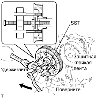
Using SST, remove the crankshaft pulley and pulley bolt.
- SST
- 09950-50013(09951-05010,09952-05010,09953-05020,09954-05021)
- УКАЗАНИЕ:
- If necessary, remove the pulley and pulley bolt using SST.
| 35. REMOVE NO. 1 CHAIN TENSIONER ASSEMBLY |
Remove the 2 nuts, bracket, tensioner and gasket.
- ПРИМЕЧАНИЕ:
- Do not turn the crankshaft without the chain tensioner.
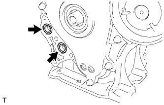
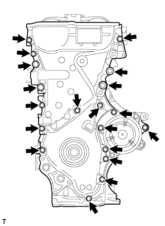
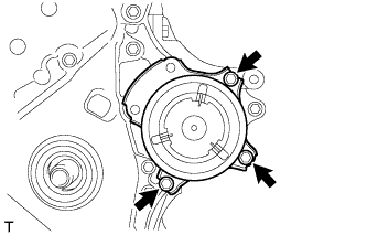
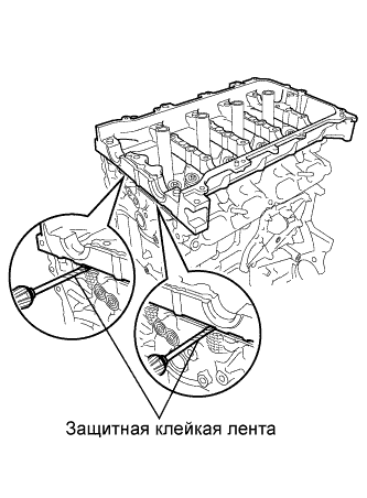
| 36. REMOVE TIMING CHAIN COVER SUB-ASSEMBLY |
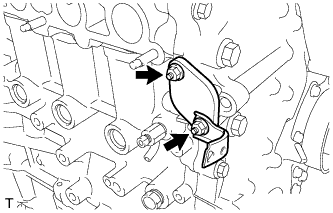
Выверните 3 болта и снимите кронштейн опоры двигателя.
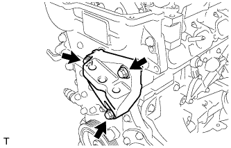
Выверните 4 болта и снимите кронштейн масляного фильтра.
Снимите 2 кольцевых уплотнения.
Выверните 19 болтов.
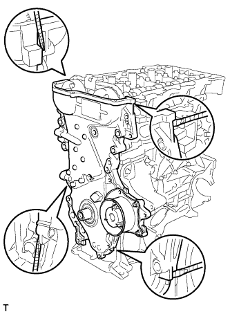
Снимите крышку цепного привода ГРМ, вставив отвертку между крышкой цепного привода и головкой блока цилиндров или блоком цилиндров.
- ПРИМЕЧАНИЕ:
- Соблюдайте осторожность, чтобы не повредить сопрягающиеся поверхности крышки цепного привода газораспределительного механизма, блока цилиндров и головки блока цилиндров.
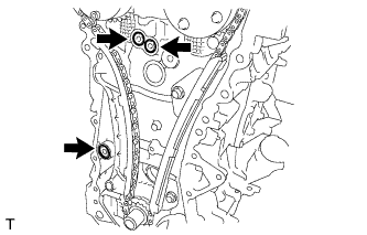
Снимите 3 кольцевых уплотнения.
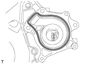
Выверните 3 болта и снимите водяной насос.
Снимите прокладку.
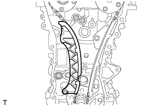
| 37. REMOVE CHAIN TENSIONER SLIPPER |
Remove the chain tensioner slipper.
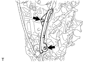
| 38. REMOVE NO. 1 CHAIN VIBRATION DAMPER |
Remove the 2 bolts and No. 1 chain vibration damper.
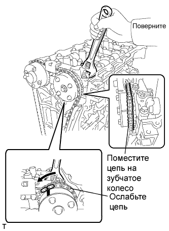
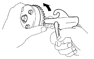
| 39. REMOVE CHAIN SUB-ASSEMBLY |
Hold the hexagonal portion of the camshaft with a wrench and turn the camshaft timing gear assembly counterclockwise to loosen the chain between the camshaft timing gears.
With the chain loosened, release the chain from the camshaft timing gear assembly and place it on the camshaft timing gear assembly.
- УКАЗАНИЕ:
- Be sure to release the chain from the sprocket completely.
Turn the camshaft clockwise to return it to the original position and remove the chain.
| 40. REMOVE NO. 2 CHAIN VIBRATION DAMPER |
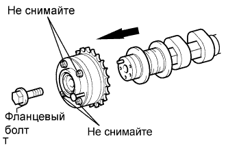
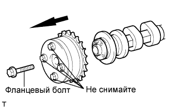
| 41. REMOVE CAMSHAFT TIMING EXHAUST GEAR ASSEMBLY |
Remove the flange bolt while holding the hexagonal portion of the camshaft, and then remove the camshaft timing exhaust gear assembly.
- ПРИМЕЧАНИЕ:
- Be sure not to remove the other 4 bolts.
- Keep the camshaft timing exhaust gear assembly horizontal while removing it from the camshaft.
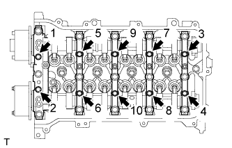
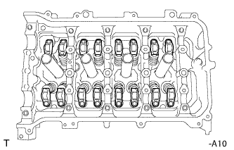
| 42. REMOVE CAMSHAFT BEARING CAP |
Uniformly loosen and remove the 10 bearing cap bolts in the sequence shown in the illustration.
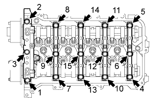
Uniformly loosen and remove the 15 bearing cap bolts in the sequence shown in the illustration.
- ПРИМЕЧАНИЕ:
- Uniformly loosen the bolts while keeping the camshaft level.
Remove the 5 bearing caps.
- УКАЗАНИЕ:
- Arrange the removed parts in the correct order.
| 43. REMOVE NO. 1 VALVE ROCKER ARM SUB-ASSEMBLY |
Remove the 16 valve rocker arms.
- УКАЗАНИЕ:
- Arrange the removed parts in the correct order.
| 44. REMOVE VALVE LASH ADJUSTER ASSEMBLY |
Remove the 16 valve lash adjusters from the cylinder head.
- УКАЗАНИЕ:
- Arrange the removed parts in the correct order.
| 45. REMOVE CAMSHAFT TIMING GEAR ASSEMBLY |
Check the lock of the camshaft timing gear.
Release the lock pin.
- ПРИМЕЧАНИЕ:
- Before removing the camshaft timing gear assembly, make sure that the lock pin has been released.
Cover the 4 oil paths of the cam journal with vinyl tape as shown in the illustration.
- УКАЗАНИЕ:
- There are 4 oil paths in the groove of the camshaft. Plug three of the paths with pieces of rubber.
Prick a hole in the tape placed on the advance side. Prick a hole in the tape placed on the retard side path, on the opposite side to that of the advance side path, as shown in the illustration.
While applying approximately 150 kPa (2.0 kgf/cm2, 22 psi) of air pressure to the oil paths, forcibly turn the camshaft timing gear assembly in the advance direction (counterclockwise).
- ПРЕДОСТЕРЕЖЕНИЕ:
- Cover the paths with a piece of cloth when applying pressure to keep oil from splashing.
- ПРИМЕЧАНИЕ:
- Do not lock the camshaft timing gear assembly. If it is locked, release the lock pin again.
- УКАЗАНИЕ:
- The camshaft timing gear assembly may be turned in the advance direction without applying any force.
- If enough air pressure cannot be applied because of air leakage from the port, releasing the lock pin may be difficult.
Remove the electrical tape and rubber pieces from the camshaft.
Install the camshafts (See page Нажмите здесь).
Remove the flange bolt while holding the hexagonal portion of the camshaft, and then remove the camshaft timing gear assembly.
- ПРИМЕЧАНИЕ:
- Before removing the camshaft timing gear, make sure that the lock pin has been released.
- Be sure not to remove the other 4 bolts.
- Keep the camshaft timing gear assembly horizontal while removing it from the camshaft.
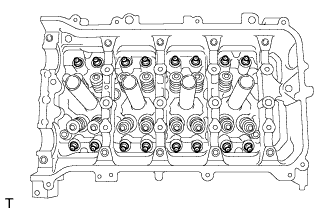
Uniformly loosen and remove the 10 bearing cap bolts in the sequence shown in the illustration.
Uniformly loosen and remove the 15 bearing cap bolts in the sequence shown in the illustration.
- ПРИМЕЧАНИЕ:
- Uniformly loosen the bolts while keeping the camshaft level.
Remove the 5 bearing caps.
- УКАЗАНИЕ:
- Arrange the removed parts in the correct order.
Remove the camshaft.
| 47. REMOVE NO. 2 CAMSHAFT |
Remove the No. 2 camshaft.
| 48. REMOVE NO. 1 CAMSHAFT BEARING |
Remove the 2 No. 1 camshaft bearings.
| 49. REMOVE NO. 2 CAMSHAFT BEARING |
Remove the 2 No. 2 camshaft bearings.
| 50. REMOVE CAMSHAFT HOUSING SUB-ASSEMBLY |
Remove the 2 bolts.
Remove the camshaft housing by prying between the cylinder head and camshaft housing with a screwdriver.
- ПРИМЕЧАНИЕ:
- Be careful not to damage the contact surfaces of the cylinder head and camshaft housing.
- УКАЗАНИЕ:
- Tape the screwdriver tip before use.
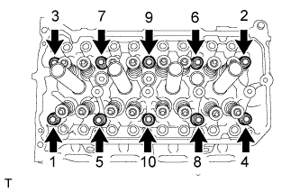
| 51. REMOVE CYLINDER HEAD SUB-ASSEMBLY |
Using several steps, uniformly loosen and remove the 10 cylinder head bolts and 10 plate washers with a 10 mm bi-hexagon wrench in the sequence shown in the illustration.
- ПРИМЕЧАНИЕ:
- Head warpage or cranking could result from removing the bolts in the wrong order.
Using a screwdriver with its tip wrapped with tape, pry between the cylinder head and cylinder block, and remove the cylinder head.
- ПРИМЕЧАНИЕ:
- Be careful not to damage the contact surfaces of the cylinder head and cylinder block.
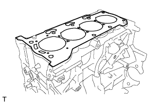
| 52. REMOVE CYLINDER HEAD GASKET |
Remove the cylinder head gasket.
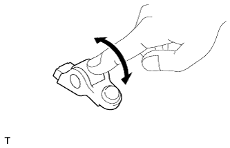
| 53. INSPECT NO. 1 VALVE ROCKER ARM SUB-ASSEMBLY |
Turn the roller by hand to check that it turns smoothly.
- УКАЗАНИЕ:
- If the roller does not turn smoothly, replace the valve rocker arm sub-assembly.
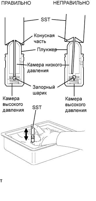
| 54. INSPECT VALVE LASH ADJUSTER ASSEMBLY |
- ПРИМЕЧАНИЕ:
- Keep the lash adjuster free of dirt and foreign objects.
- Only use clean engine oil.
Place the lash adjuster into a container filled with engine oil.
Insert the SST's tip into the lash adjuster's plunger and use the tip to press down on the check ball inside the plunger.
- SST
- 09276-75010
Squeeze SST and lash adjuster together to move the plunger up and down 5 to 6 times.
Check the movement of the plunger and bleed it.
- OK:
- Plunger moves up and down.
- ПРИМЕЧАНИЕ:
- When bleeding the high-pressure chamber, make sure that the tip of SST is actually pressing the check ball as shown in the illustration. If the check ball is not pressed, the high-pressure chamber will not be bled.
After bleeding, remove SST. Then try to quickly and firmly press the plunger with a finger.
- OK:
- Plunger is very difficult to move.
If the result is not as specified, replace the lash adjuster.
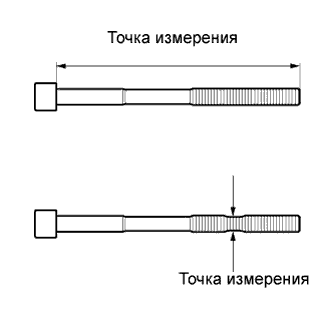
| 55. INSPECT CYLINDER HEAD SET BOLT |
Using vernier calipers, measure the length of the cylinder head set bolt from the seat to the end.
- Standard bolt length:
- 146.8 to 148.2 mm (5.7795 to 5.8346 in.)
- Maximum bolt length:
- 149.2 mm (5.874 in.)
If the bolt length is greater than the maximum, replace the cylinder head set bolt.
Using vernier calipers, measure the minimum diameter of the elongated thread at the measuring point.
- Standard outside diameter:
- 9.77 to 9.96 mm (0.3846 to 0.3921 in.)
- Minimum outside diameter:
- 9.4 mm (0.3701 in.)
- УКАЗАНИЕ:
- Using a straightedge, visually check for thinner areas of the threaded part of the cylinder head set bolt.
If the diameter is less than the minimum, replace the cylinder head set bolt.