INSTALL DRIVE PLATE AND RING GEAR SUB-ASSEMBLY (for Automatic Transaxle)
INSPECT AND ADJUST CLUTCH COVER ASSEMBLY (for Manual Transaxle)
INSTALL AUTOMATIC TRANSAXLE ASSEMBLY (for Automatic Transaxle)
Прокладка Головки Блока Цилиндров -- Установка |
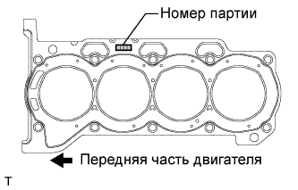
| 1. INSTALL CYLINDER HEAD GASKET |
Place a new gasket on the cylinder block surface with the Lot No. stamp facing upward.
- ПРИМЕЧАНИЕ:
- Remove any oil from the contact surface.
- Make sure that the gasket is installed in the correct direction.
 |
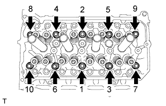
| 2. INSTALL CYLINDER HEAD SUB-ASSEMBLY |
- УКАЗАНИЕ:
- The cylinder head bolts are tightened in 2 progressive steps.
Apply a light coat of engine oil to the bolt threads and the area beneath the bolt heads that come in contact with the washers.
Install the bolts and plate washers to the cylinder head.
- ПРИМЕЧАНИЕ:
- Do not drop the washers into the cylinder head.
Using several passes, uniformly install and tighten the 10 cylinder head set bolts and plate washers with a 10 mm bi-hexagon wrench in the order shown in the illustration.
- Момент затяжки:
- 49 Н*м{500 кгс*см, 36 фунт-сила-футов}
 |
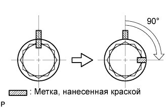
Mark the front side of the cylinder head bolt with paint.
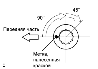 |
Retighten the cylinder head bolts by additional 90° and one more additional 45° as shown in the illustration.
Check that the paint mark is now at a 135° angle to the front.
| 3. INSTALL VALVE LASH ADJUSTER ASSEMBLY |
- ПРИМЕЧАНИЕ:
- Keep the lash adjuster free of dirt and foreign objects.
- Only use clean engine oil.
Place the lash adjuster into a container filled with engine oil.
Insert the SST's tip into the lash adjuster's plunger and use the tip to press down on the check ball inside the plunger.
- SST
- 09276-75010
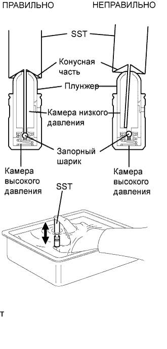 |
Squeeze SST and lash adjuster together to move the plunger up and down 5 to 6 times.
Check the movement of the plunger and bleed it.
- OK:
- Plunger moves up and down.
- ПРИМЕЧАНИЕ:
- When bleeding air from the high-pressure chamber, make sure that the tip of SST is actually pressing the check ball as shown in the illustration. If the check ball is not pressed, the high-pressure chamber will not be bled.
After bleeding, remove SST. Then, try to press the plunger quickly and firmly with a finger.
- OK:
- Plunger is very difficult to move.
Install the lash adjusters.
- ПРИМЕЧАНИЕ:
- Install the lash adjuster to the same place it was removed from.
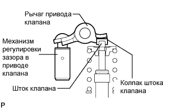
| 4. INSTALL NO. 1 VALVE ROCKER ARM SUB-ASSEMBLY |
Apply engine oil to the lash adjuster tip and valve stem cap end.
Make sure that the valve rocker arms are installed as shown in the illustration.
 |
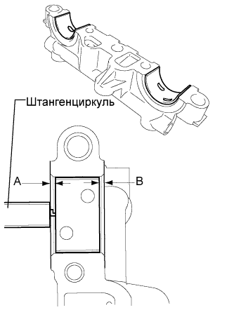
| 5. INSTALL NO. 1 CAMSHAFT BEARING |
Clean the both surfaces of the bearing.
Install the 2 No. 1 camshaft bearings.
Using vernier calipers, measure the distance between the bearing cap's edge and the camshaft bearing's edge.
- Dimension (A - B):
- 0.7 mm (0.0276 in.) or less
- ПРИМЕЧАНИЕ:
- Position the bearing to the center of the bearing cap by measuring dimension A - B.
 |
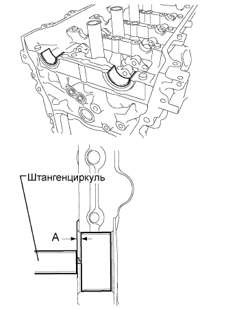
| 6. INSTALL NO. 2 CAMSHAFT BEARING |
Clean the both surfaces of the bearing.
Install the 2 No. 2 camshaft bearings.
Using vernier calipers, measure the distance between the bearing cap's edge and the camshaft bearing's edge.
- Dimension (A):
- 1.05 to 1.75 mm (0.041 to 0.069 in.)
- ПРИМЕЧАНИЕ:
- Position the bearing to the center of the bearing cap by measuring dimension A.
 |
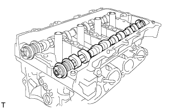
| 7. INSTALL NO. 2 CAMSHAFT |
Clean the camshaft journals.
Apply a light coat of engine oil to the camshaft journals, camshaft housings and bearing caps.
Install the No. 2 camshaft to the camshaft housing.
 |
| 8. INSTALL CAMSHAFT |
Clean the camshaft journals.
Apply a light coat of engine oil to the camshaft journals, camshaft housings and bearing caps.
Install the camshaft to the camshaft housing.
 |
| 9. INSTALL CAMSHAFT BEARING CAP |
Apply engine oil to the camshaft journals, camshaft housing and bearing caps.
Make sure of the marks and numbers on the camshaft bearing caps and place them in each proper position and direction.
- УКАЗАНИЕ:
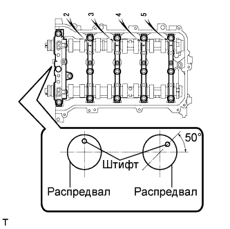
- Make sure that the knock pin of the camshaft is positioned as shown in the illustration.
 |
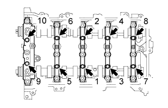
Tighten the 10 bolts in the order shown in the illustration.
- Момент затяжки:
- 16 Н*м{163 кгс*см, 12 фунт-сила-футов}
 |
| 10. INSTALL CAMSHAFT HOUSING SUB-ASSEMBLY |
Make sure that the valve rocker arm is installed as shown in the illustration.
|
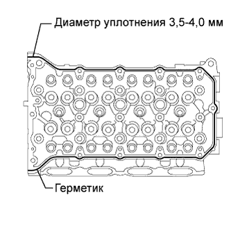
Apply seal packing in a continuous line as shown in the illustration.
- Seal packing:
- Toyota Genuine Seal Packing Black, Three Bond 1207B or equivalent
- Seal diameter:
- 3.5 to 4.0 mm (0.138 to 0.158 in.)
- ПРИМЕЧАНИЕ:
- Remove any oil from the contact surface.
- Install the camshaft housing sub-assembly RH within 3 minutes.
- Do not start the engine for at least 2 hours after installing.
 |
Set the camshaft and No. 2 camshaft as shown in the illustration.
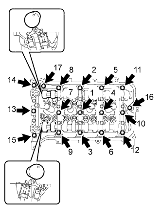 |
Install the camshaft housing and tighten the 17 bolts in the order shown in the illustration.
- Момент затяжки:
- 27 Н*м{275 кгс*см, 20 фунт-сила-футов}
- ПРИМЕЧАНИЕ:
- After installing the camshaft housing, make sure that the cam lobes are positioned as shown in the illustration.
- If any of the bolts are loosened during installation, remove the camshaft housing, clean the installation surfaces, and reapply seal packing.
- If the camshaft housing is removed because any of the bolts are loosened during installation, make sure that the previously applied seal packing does not enter any oil passages.
- After installing the camshaft housing, wipe off any seal packing that seeped out from between the housing and the cylinder head.
| 11. INSTALL CAMSHAFT TIMING GEAR ASSEMBLY |
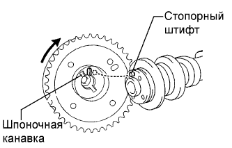
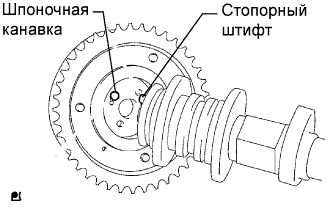
Check that the knock pin is installed on the camshaft.
Put the camshaft timing gear and camshaft together with the straight pin and key groove misaligned, as shown in the illustration.
- ПРИМЕЧАНИЕ:
- Do not forcefully push in the camshaft timing gear assembly. This may cause the camshaft knock pin tip to damage the installation surface of the camshaft timing gear assembly.
 |
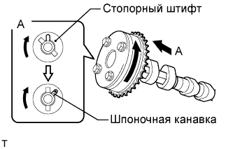
Turn the camshaft timing gear as shown in the illustration while pushing it gently against the camshaft. Push further at the position where the pin fits into the groove.
- ПРИМЕЧАНИЕ:
- Do not turn the camshaft timing gear in the retard direction (the right angle).
 |
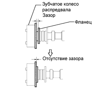
Check that there is no clearance between the gear and camshaft.
 |
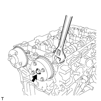
Tighten the flange bolt with the camshaft timing gear fixed in place.
- Момент затяжки:
- 54 Н*м{551 кгс*см, 40 фунт-сила-футов}
 |
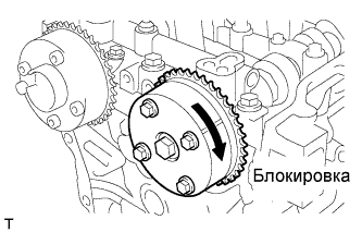
Check that the camshaft timing gear can move to the retard angle side (the right direction) and is locked in the most retarded position.
 |
| 12. INSTALL CAMSHAFT TIMING EXHAUST GEAR ASSEMBLY |
Check that the knock pin is installed on the camshaft.
Put the camshaft timing exhaust gear and camshaft together by aligning the key groove and straight pin.
 |
Lightly press the gear against the camshaft, and turn the gear. Push further at the position where the pin enters the groove.
- ПРИМЕЧАНИЕ:
- Be sure not to turn the camshaft timing exhaust gear in the retard direction (the right angle).
Check that there is no clearance between the gear's flange and the camshaft.
Tighten the flange bolt with the camshaft timing exhaust gear fixed.
- Момент затяжки:
- 54 Н*м{551 кгс*см, 40 фунт-сила-футов}
 |
Check the camshaft timing exhaust gear lock.
Make sure that the camshaft timing exhaust gear is locked.
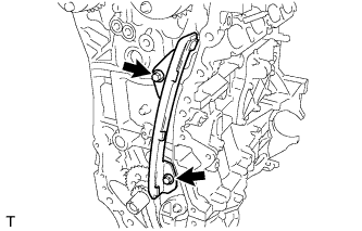
| 13. INSTALL NO. 1 CHAIN VIBRATION DAMPER |
Install the No. 1 chain vibration damper with the 2 bolts.
- Момент затяжки:
- 21 Н*м{214 кгс*см, 16 фунт-сила-футов}
 |
| 14. INSTALL NO. 2 CHAIN VIBRATION DAMPER |
| 15. INSTALL CHAIN SUB-ASSEMBLY |
Check the No. 1 cylinder TDC/compression.
Temporarily tighten the crankshaft pulley bolt.
Turn the crankshaft counterclockwise to position the timing gear key to the top.
Remove the crankshaft pulley bolt.
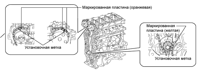
Check the timing marks on each camshaft timing gear.
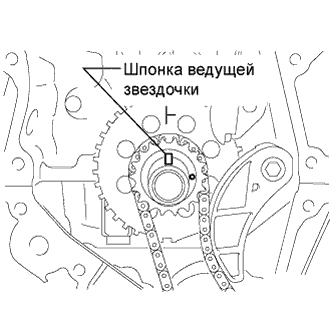

Align the mark plate (orange) with the timing mark as shown in the illustration and install the chain.
- УКАЗАНИЕ:
- Be sure to position the mark plate at the front of the engine.
- The mark plate on the camshaft side is colored orange.
- Do not pass the chain around the sprocket of the camshaft timing gear assembly. Only place it on the sprocket.
- Pass the chain through the No. 1 vibration damper.
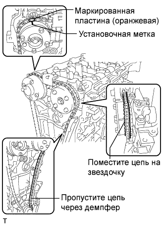 |
Place the chain on the crankshaft without passing it around the shaft.
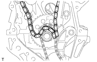 |
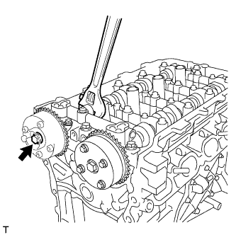
Hold the hexagonal portion of the camshaft with a wrench and turn the camshaft timing gear assembly counterclockwise to align the mark plate (orange) and timing mark.
- УКАЗАНИЕ:
- Be sure to position the mark plate at the front of the engine.
- The mark plate on the camshaft side is colored orange.
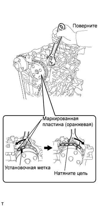 |
Hold the hexagonal portion of the camshaft with a wrench and turn the camshaft timing gear assembly clockwise.
- УКАЗАНИЕ:
- To tension the chain, slowly turn the camshaft timing gear assembly clockwise to prevent the chain from being misaligned.
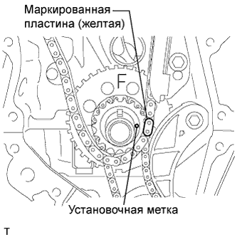
Align the mark plate (yellow) and timing mark and install the chain to the crankshaft timing gear.
- УКАЗАНИЕ:
- The mark plate on the crankshaft side is colored yellow.
 |
Recheck each timing mark at TDC/compression.
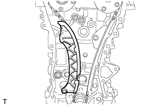
| 16. INSTALL CHAIN TENSIONER SLIPPER |
Install the chain tensioner slipper.
 |
| 17. INSTALL TIMING CHAIN COVER SUB-ASSEMBLY |
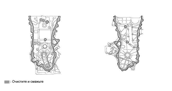
Remove any old packing (FIPG) material and be careful not to drop any oil on the contact surfaces of the timing chain cover, cylinder head, and cylinder block.
Install 3 new O-rings.
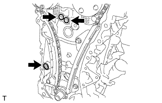 |
Apply seal packing as shown in the illustration.
- Seal packing:
- Toyota Genuine Seal Packing Black, Three Bond 1207B or equivalent
- Seal diameter:
- 3.0 mm (0.118 in.)
- ПРИМЕЧАНИЕ:
- Remove any oil from the contact surface.
- Install the chain cover within 3 minutes after applying seal packing.
- Do not start the engine for at least 2 hours after installing the timing chain cover sub-assembly.
Apply seal packing to the timing chain cover in a continuous line as shown in the following illustration.
- ПРИМЕЧАНИЕ:
- When the contact surfaces are wet, wipe them with oil-free cloth before applying seal packing.
- Install the chain cover within 3 minutes and tighten the bolts within 15 minutes after applying seal packing.
- Do not start the engine for at least 2 hours after installing.
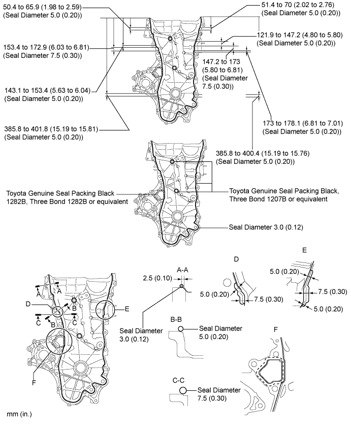
- Apply seal packing as follows:
Area Seal Packing Diameter Application Position from Inside Seal Line Seal packing Continuous Line Area 3.0 mm (0.118 in.) 2.5 mm (0.098 in.) Toyota Genuine Seal Packing Black, Three Bond 1207B or equivalent Dashed Line Area 4.0 mm (0.156 in.) 3.0 mm (0.118 in.) Toyota Genuine Seal Packing Black 1282B, Three Bond 1282B or equivalent
Install the timing chain cover.
Install a new gasket.
- ПРИМЕЧАНИЕ:
- Remove any oil from the contact surface.
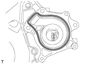 |
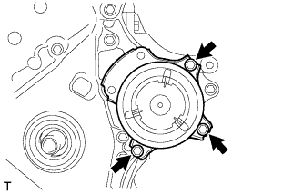
Install the water pump with the 3 bolts.
- Момент затяжки:
- 21 Н*м{214 кгс*см, 16 фунт-сила-футов}
 |
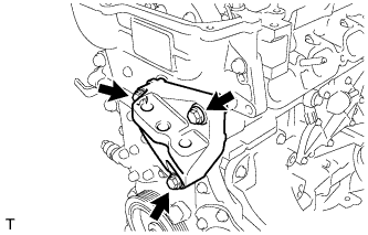
Install the engine mounting bracket with the 3 bolts.
- ПРИМЕЧАНИЕ:
- Install the mounting bracket within 10 minutes after installing the chain cover.
- Do not start the engine for at least 2 hours after installation.
- Bolt length:
Item Length Bolt 80 mm (3.15 in.)
 |
Install 2 new O-rings.
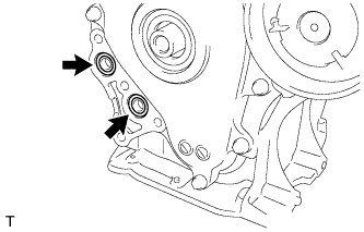 |
Temporarily tighten the oil filter bracket with the 4 bolts.
- ПРИМЕЧАНИЕ:
- Install the oil filter bracket within 10 minutes after installing the chain cover.
- Do not start the engine for at least 2 hours after installation.
- Bolt length:
Item Length Bolt 35 mm (1.38 in.)
 |
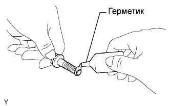
Apply adhesive to the threads of the bolt E.
- Adhesive:
- Toyota Genuine Adhesive 1324, Three Bond 1324 or equivalent
Install the timing chain cover with the 26 bolts as shown in the illustration.
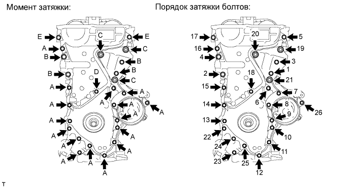
- Момент затяжки:
- Bolt A, E:
- 21 Н*м{214 кгс*см, 16 фунт-сила-футов}
- Bolt B:
- 43 Н*м{439 кгс*см, 32 фунт-сила-футов}
- Bolt C:
- 43 Н*м{439 кгс*см, 32 фунт-сила-футов}
- Bolt D:
- 10 Н*м{102 кгс*см, 7 фунт-сила-футов}
- ПРИМЕЧАНИЕ:
- When the contact surfaces are wet, wipe them with oil-free cloth before applying seal packing.
- Install the chain cover within 3 minutes and tighten the bolts within 15 minutes after applying the seal packing.
- Do not start the engine for at least 2 hours after installing.
- Bolt length:
Item Length Bolt A, E 35 mm (1.38 in.) Bolt B 55 mm (2.16 in.) Bolt C 80 mm (3.15 in.) Bolt D 40 mm (1.57 in.)
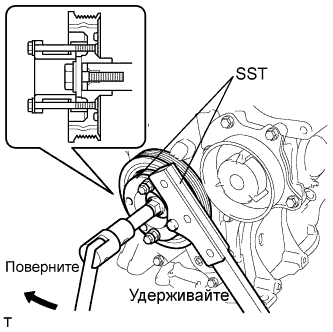
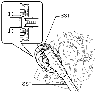
| 18. INSTALL CRANKSHAFT PULLEY |
Align the pulley set key with the key groove of the pulley.
Using SST, hold the pulley in place and tighten the bolt.
- SST
- 09213-54015(91651-60855)
09330-00021
- Момент затяжки:
- 190 Н*м{1940 кгс*см, 140 фунт-сила-футов}
 |
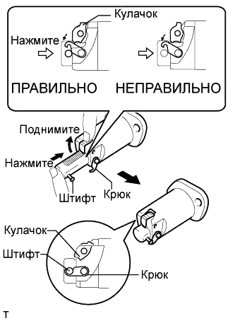
| 19. INSTALL NO. 1 CHAIN TENSIONER ASSEMBLY |
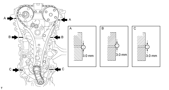
Release the ratchet pawl, then fully push in the plunger and hook the hook to the pin so that the plunger is in the position shown in the illustration.
- ПРИМЕЧАНИЕ:
- Make sure that the cam engages the first tooth of the plunger to allow the hook to pass over the pin.
 |
Install a new gasket, bracket and the No. 1 chain tensioner with the 2 nuts.
- Момент затяжки:
- 10 Н*м{102 кгс*см, 7 фунт-сила-футов}
- ПРИМЕЧАНИЕ:
- If the hook releases the plunger while the chain tensioner is being installed, set the hook again.
 |
Turn the crankshaft counterclockwise, then disconnect the plunger knock pin from the hook.
 |
Turn the crankshaft clockwise, then check that the plunger is extended.
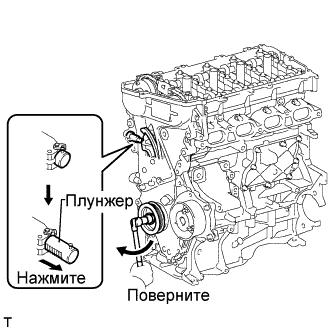 |
| 20. INSTALL CYLINDER HEAD COVER GASKET |
Install the gasket to the cylinder head cover.
- ПРИМЕЧАНИЕ:
- Remove any oil from the contact surface.
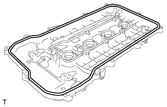 |
| 21. INSTALL CYLINDER HEAD COVER SUB-ASSEMBLY |
Install 3 new gaskets to the No. 1 camshaft bearing cap.
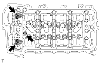 |
Apply seal packing as shown the illustration.
- Seal packing:
- Toyota Genuine Seal Packing Black, Three Bond 1207B or equivalent
- ПРИМЕЧАНИЕ:
- Remove any oil from the contact surface.
- Install the cylinder head cover within 3 minutes and tighten the bolts within 15 minutes after applying seal packing.
- Do not start the engine for at least 2 hours after the installation.
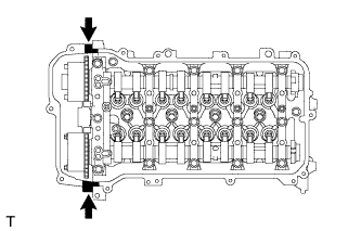 |
Install the cylinder head cover with a new seal washer and the 13 bolts.
- Момент затяжки:
- 10 Н*м{102 кгс*см, 7 фунт-сила-футов}
 |
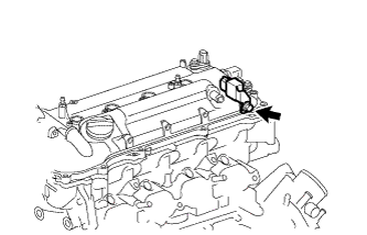
| 22. INSTALL RADIO SETTING CONDENSER |
Install the radio setting condenser with the bolt.
- Момент затяжки:
- 10 Н*м{102 кгс*см, 7 фунт-сила-футов}
 |
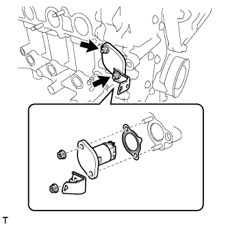
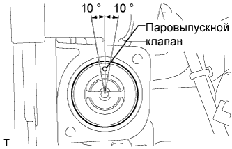
| 23. INSTALL THERMOSTAT |
Install a new gasket on the thermostat.
Install the thermostat to the water inlet.
- ПРИМЕЧАНИЕ:
- The jiggle valve may be set within 10° on either side of the prescribed position.
 |
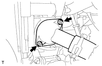
| 24. INSTALL WATER INLET |
Install the water inlet with the 2 nuts.
- Момент затяжки:
- 10 Н*м{102 кгс*см, 7 фунт-сила-футов}
 |
| 25. INSTALL WATER INLET HOSE |
Install the water inlet hose with the 2 clamps.
 |
| 26. INSTALL WATER BY-PASS HOSE |
Install the water by-pass hose with the clamp.
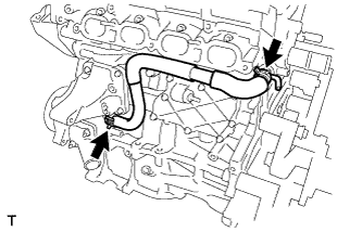
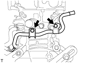
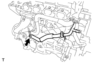
| 27. INSTALL NO. 1 WATER BY-PASS PIPE |
Install the No. 1 water by-pass pipe with the 2 bolts.
- Момент затяжки:
- 21 Н*м{214 кгс*см, 16 фунт-сила-футов}
 |
| 28. INSTALL NO. 3 WATER BY-PASS HOSE |
Connect the No. 3 water by-pass hose to the water inlet housing.
 |
| 29. INSTALL VENTILATION HOSE |
Install the ventilation hose.
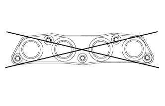
| 30. INSPECT EXHAUST MANIFOLD |
Using a precision straightedge and feeler gauge, measure the warpage on the contact surface of the cylinder head.
- Maximum warpage:
- 0.7 mm (0.028 in.)
- УКАЗАНИЕ:
- If the warpage is greater than the maximum, replace the manifold.
 |
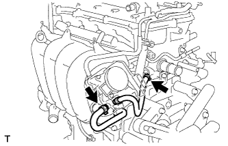
| 31. INSTALL EXHAUST MANIFOLD |
Install a new gasket onto the exhaust manifold.
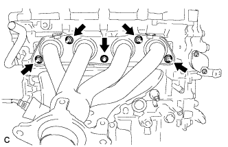 |
Install the exhaust manifold with the 5 nuts.
- Момент затяжки:
- 21 Н*м{214 кгс*см, 16 фунт-сила-футов}
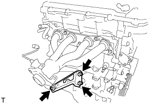
| 32. INSTALL MANIFOLD STAY |
Install the manifold stay with the 3 bolts.
- Момент затяжки:
- 43 Н*м{439 кгс*см, 32 фунт-сила-футов}
 |
| 33. INSTALL NO. 1 EXHAUST MANIFOLD HEAT INSULATOR |
Install the exhaust manifold heat insulator with the 4 bolts.
- Момент затяжки:
- 12 Н*м{122 кгс*см, 9 фунт-сила-футов}
 |
| 34. INSTALL OIL LEVEL GAUGE SUB-ASSEMBLY |
Apply engine oil to a new O-ring.
 |
Install the oil level gauge with the bolt through a new O-ring.
- Момент затяжки:
- 21 Н*м{214 кгс*см, 16 фунт-сила-футов}
| 35. INSTALL IGNITION COIL ASSEMBLY |
Install the 4 ignition coils with the 4 bolts.
- Момент затяжки:
- 10 Н*м{102 кгс*см, 7 фунт-сила-футов}
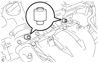
| 36. INSTALL FUEL INJECTOR ASSEMBLY |
Install the 2 No. 1 delivery pipe spacers onto the cylinder head.
- ПРИМЕЧАНИЕ:
- Install the No. 1 delivery pipe spacers in the correct direction.
 |
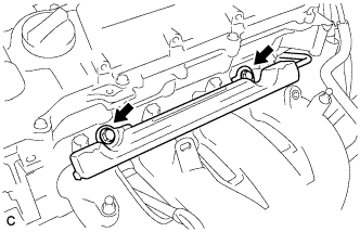
| 37. INSTALL NO. 1 DELIVERY PIPE SPACER |
Install the 2 No. 1 delivery pipe spacers onto the cylinder head.
- ПРИМЕЧАНИЕ:
- Install the No. 1 delivery pipe spacers in the correct direction.
|
| 38. INSTALL FUEL DELIVERY PIPE SUB-ASSEMBLY |
Install the fuel delivery pipe sub-assembly with the 4 fuel injector assemblies then temporarily install the 2 bolts.
- ПРИМЕЧАНИЕ:
- Do not drop the fuel injectors when installing the fuel delivery pipe sub-assembly.
- Check that the fuel injector assemblies rotate smoothly after installing the fuel delivery pipe sub-assembly.
 |
Tighten the 2 bolts to the specified torque.
- Момент затяжки:
- 21 Н*м{214 кгс*см, 15 фунт-сила-футов}
|
Install the bolt to secure the fuel delivery pipe sub-assembly.
- Момент затяжки:
- 21 Н*м{214 кгс*см, 15 фунт-сила-футов}
 |
Install the wire harness bracket with the bolt.
 |
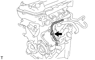
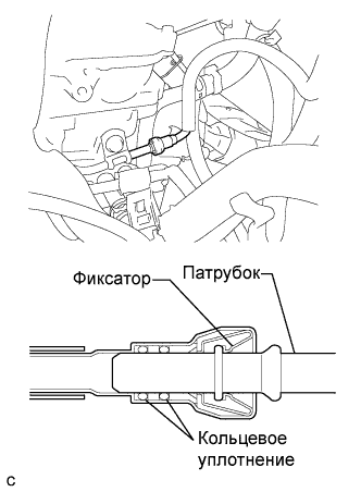
| 39. INSTALL FUEL TUBE SUB-ASSEMBLY |
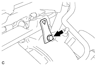
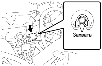
Insert the fuel tube sub-assembly connector into the fuel delivery pipe until a "click" sound can be heard.
- ПРИМЕЧАНИЕ:
- Check that there are no scratches or foreign matter around the disconnected parts of the fuel tube connector and pipe before performing this work.
- After connecting the fuel tube, check that the fuel tube connector and pipe are securely connected by pulling them.
 |
Install a new No. 2 fuel pipe clamp (Type B).
 |
Install a new No. 2 fuel pump clamp (Type A).
 |
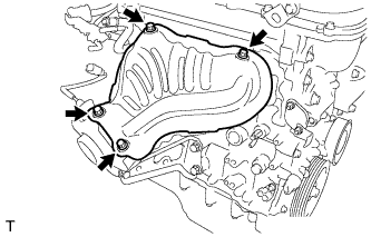
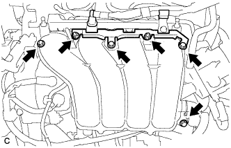
| 40. INSTALL INTAKE MANIFOLD |
Install a new gasket to the intake manifold.
Install the intake manifold and intake manifold stay with the 3 bolts and 2 nuts.
- Момент затяжки:
- 28 Н*м{286 кгс*см, 21 фунт-сила-футов}
 |
Connect the 2 water by-pass hoses.
 |
Connect the ventilation hose to the intake manifold.
Install the air tube with the 2 bolts.
- Момент затяжки:
- 10 Н*м{102 кгс*см, 7 фунт-сила-футов}
install the wire harness bracket.
- Момент затяжки:
- 10 Н*м{102 кгс*см, 7 фунт-сила-футов}
| 41. REMOVE ENGINE STAND |
Attach the sling device and the engine with the chain block.
Remove the engine from the engine stand.
| 42. INSTALL ENGINE WIRE |
| 43. INSTALL FLYWHEEL SUB-ASSEMBLY (for Manual Transaxle) |
Using SST, hold the crankshaft.
- SST
- 09213-54015(91651-60855)
09330-00021
 |
Apply adhesive to the 2 or 3 end threads of the new bolts.
- Adhesive:
- Toyota Genuine Adhesive 1324, Three Bond 1324 or equivalent
 |
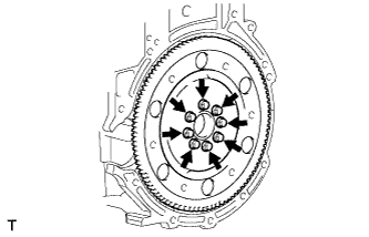
Using several steps, uniformly install and tighten the 8 bolts in the sequence shown in the illustration.
- Момент затяжки:
- 49 Н*м{500 кгс*см, 36 фунт-сила-футов}
 |
Mark the front of the bolts with paint.
 |
Retighten the 8 bolts by 90° in the same sequence.
Check that the paint marks are now at a 90° angle to the front.
Check that the crankshaft turns smoothly.
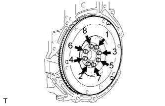
| 44. INSTALL DRIVE PLATE AND RING GEAR SUB-ASSEMBLY (for Automatic Transaxle) |
Using SST, hold the crankshaft.
- SST
- 09213-54015(91651-60855)
09330-00021
|
Clean the bolt and the bolt hole.
Apply adhesive to 2 or 3 threads of the bolt end.
- Adhesive:
- Toyota Genuine Adhesive 1324, Three Bond 1324 or equivalent
Install the front spacer, drive plate and rear spacer with the 8 bolts. Uniformly tighten the 8 bolts.
- Момент затяжки:
- 88 Н*м{897 кгс*см, 65 фунт-сила-футов}
 |
| 45. INSTALL CLUTCH DISC ASSEMBLY (for Manual Transaxle) |
- УКАЗАНИЕ:
- See page Нажмите здесь for C66.
| 46. INSTALL CLUTCH COVER ASSEMBLY (for Manual Transaxle) |
- УКАЗАНИЕ:
- See page Нажмите здесь for C66.
| 47. INSPECT AND ADJUST CLUTCH COVER ASSEMBLY (for Manual Transaxle) |
- УКАЗАНИЕ:
- See page Нажмите здесь for C66.
| 48. INSTALL MANUAL TRANSAXLE ASSEMBLY (for Manual Transaxle) |
- УКАЗАНИЕ:
- See page Нажмите здесь for C66.
| 49. INSTALL AUTOMATIC TRANSAXLE ASSEMBLY (for Automatic Transaxle) |
- УКАЗАНИЕ:
- See page Нажмите здесь for U341E.
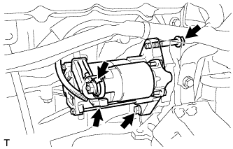
| 50. INSTALL STARTER ASSEMBLY |
Install the starter assembly with the 2 bolts.
- Момент затяжки:
- 37 Н*м{377 кгс*см, 27 фунт-сила-футов}
 |
Connect the connector.
Connect terminal 30 with the nut.
- Момент затяжки:
- 9.8 Н*м{100 кгс*см, 87 фунт-сила-дюймов}
Close the terminal cap.
Install the wire harness bracket with the bolt.
- Момент затяжки:
- 8.4 Н*м{85 кгс*см, 74 фунт-сила-дюймов}
 |
Install the 2 harness clamps.
| 51. INSTALL FLYWHEEL HOUSING SIDE COVER |
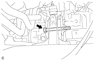
| 52. INSTALL REAR ENGINE MOUNTING INSULATOR |
Install the rear engine mounting insulator to the engine mounting bracket with the through bolt.
- Момент затяжки:
- 95 Н*м{969 кгс*см, 70 фунт-сила-футов}
 |
| 53. INSTALL ENGINE ASSEMBLY WITH TRANSAXLE |
- УКАЗАНИЕ:
- See page Нажмите здесь.