Двигатель. COROLLA, AURIS. ZZE150 ZRE151,152 NDE150
DESCRIPTION
WIRING DIAGRAM
INSPECTION PROCEDURE
CHECK HARNESS AND CONNECTOR (ECM - BODY GROUND)
INSPECT ECM (IGSW VOLTAGE)
INSPECT FUSE (EFI MAIN FUSE)
INSPECT FUSE (EFI NO. 1 FUSE)
INSPECT INTEGRATION RELAY (EFI MAIN RELAY)
CHECK HARNESS AND CONNECTOR (INTEGRATION RELAY (EFI MAIN RELAY) - EFI NO. 1 FUSE)
CHECK HARNESS AND CONNECTOR (EFI NO. 1 FUSE - ECM)
CHECK HARNESS AND CONNECTOR (EFI MAIN RELAY - BATTERY)
CHECK HARNESS AND CONNECTOR (INTEGRATION RELAY (EFI MAIN RELAY) - BODY GROUND)
CHECK HARNESS AND CONNECTOR (INTEGRATION RELAY (EFI MAIN RELAY) - ECM)
INSPECT FUSE (IGN FUSE)
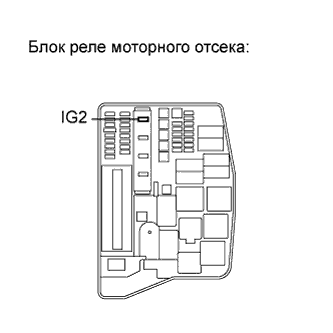
INSPECT FUSE (IG2 FUSE)
INSPECT INTEGRATION RELAY (IG2 RELAY)
CHECK HARNESS AND CONNECTOR (IGN FUSE - ECM)
CHECK HARNESS AND CONNECTOR (INTEGRATION RELAY (IG2 RELAY) - IGN FUSE)
CHECK HARNESS AND CONNECTOR (INTEGRATION RELAY (IG2 RELAY) - BATTERY)
CHECK HARNESS AND CONNECTOR (INTEGRATION RELAY (IG2 RELAY) - BODY GROUND)
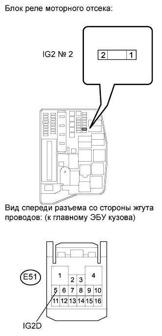
INSPECT FUSE (IG2 NO. 2 FUSE)
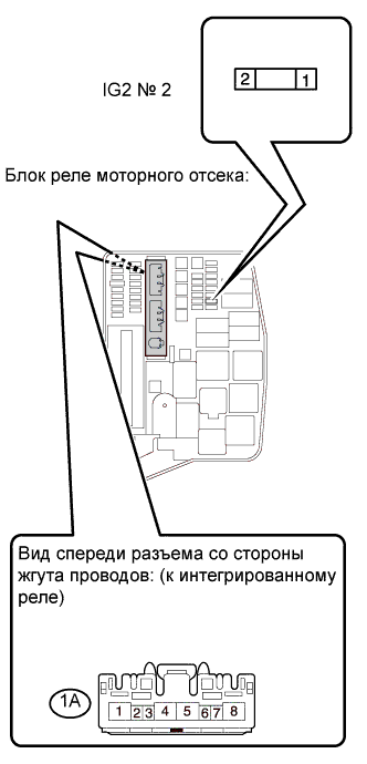
CHECK HARNESS AND CONNECTOR (IG2 RELAY - IG2 NO. 2 FUSE)
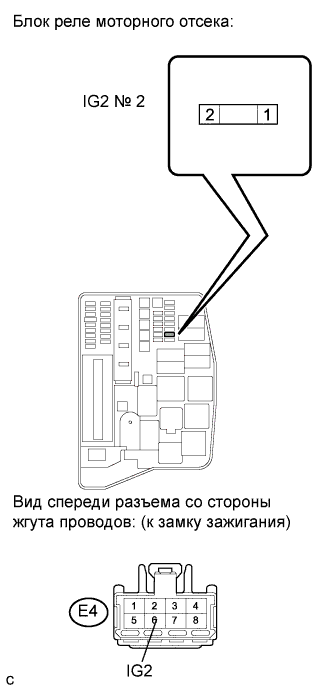
CHECK HARNESS AND CONNECTOR (IG2 NO. 2 FUSE - IGNITION SWITCH)
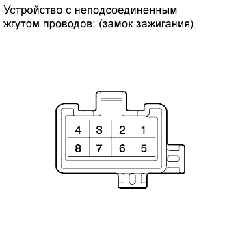
INSPECT IGNITION SWITCH ASSEMBLY
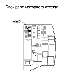
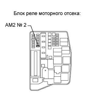
INSPECT FUSE (AM2 FUSE)
CHECK HARNESS AND CONNECTOR (IGNITION SWITCH - AM2 FUSE)
CHECK HARNESS AND CONNECTOR (IG2 NO. 2 FUSE - MAIN BODY ECU)
INSPECT FUSE (AM2 NO. 2 FUSE)
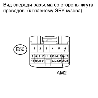
INSPECT MAIN BODY ECU (AM2 VOLTAGE)
СИСТЕМА SFI - Цепь питания ECM |
DESCRIPTION
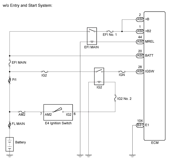
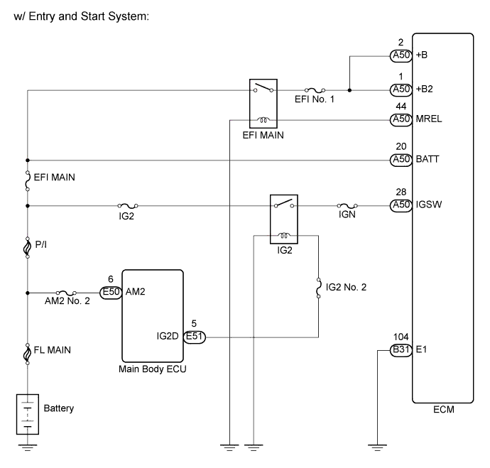
When the ignition switch is turned on (IG), the battery voltage is applied to IGSW of the ECM. The output signal from the MREL terminal of the ECM causes a current to flow to the coil, closing the contacts of the integration relay (EFI MAIN relay) and supplying power to either terminal +B or +B2 of the ECM.
WIRING DIAGRAM
INSPECTION PROCEDURE
| 1.CHECK HARNESS AND CONNECTOR (ECM - BODY GROUND) |
Disconnect the ECM connector.
Measure the resistance according to the value(s) in the table below.
- Standard resistance:
Tester Connection
| Condition
| Specified Condition
|
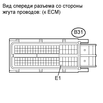
B31-104 (E1) - Body ground
| Always
| Below 1 Ω
|
Reconnect the ECM connector.
| | REPAIR OR REPLACE HARNESS OR CONNECTOR (ECM - BODY GROUND) |
|
|
| 2.INSPECT ECM (IGSW VOLTAGE) |
Disconnect the ECM connector.
Turn the ignition switch on (IG).
Measure the voltage according to the value(s) in the table below.
- Standard voltage:
Tester Connection
| Switch Condition
| Specified Condition
|
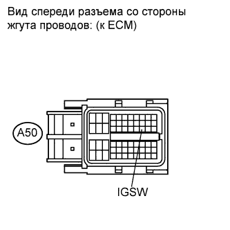
A50-28 (IGSW) - Body ground
| Ignition switch on (IG)
| 9 to 14 V
|
Reconnect the ECM connector.
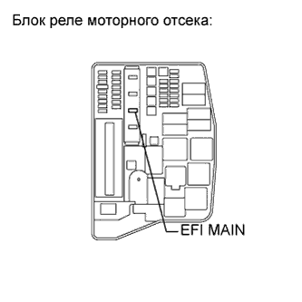
| 3.INSPECT FUSE (EFI MAIN FUSE) |
Remove the EFI MAIN fuse from the engine room relay block.
Measure the resistance according to the value(s) in the table below.
- Standard resistance:
Tester Connection
| Condition
| Specified Condition
|
EFI MAIN fuse
| Always
| Below 1 Ω
|
Reinstall the EFI MAIN fuse.
| | REPLACE FUSE (EFI MAIN FUSE) |
|
|
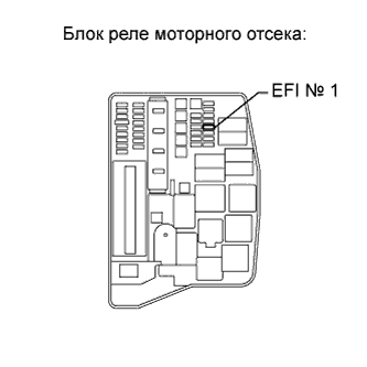
| 4.INSPECT FUSE (EFI NO. 1 FUSE) |
Remove the EFI No. 1 fuse from the engine room relay block.
Measure the resistance according to the value(s) in the table below.
- Standard resistance:
Tester Connection
| Condition
| Specified Condition
|
EFI No. 1 fuse
| Always
| Below 1 Ω
|
Reinstall the EFI No. 1 fuse.
| | REPLACE FUSE (EFI NO. 1 FUSE) |
|
|
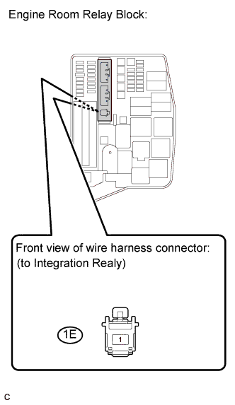
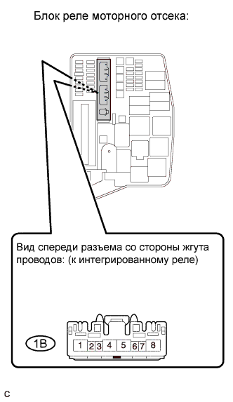
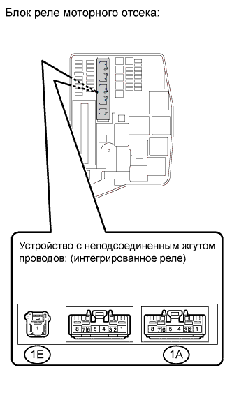
| 5.INSPECT INTEGRATION RELAY (EFI MAIN RELAY) |
Remove the integration relay from the engine room relay block.
Disconnect the integration relay connector.
Measure the EFI MAIN relay resistance.
- Standard resistance:
Tester Connection
| Condition
| Specified Condition
|
1E-1 - 1B-4
| Always
| 10 kΩ or higher
|
Always
| Below 1 Ω
(Apply battery voltage terminal 1B-2 and 1B-3)
|
Reconnect the integration relay connector.
Reinstall the integration relay.
| | REPLACE INTEGRATION RELAY |
|
|
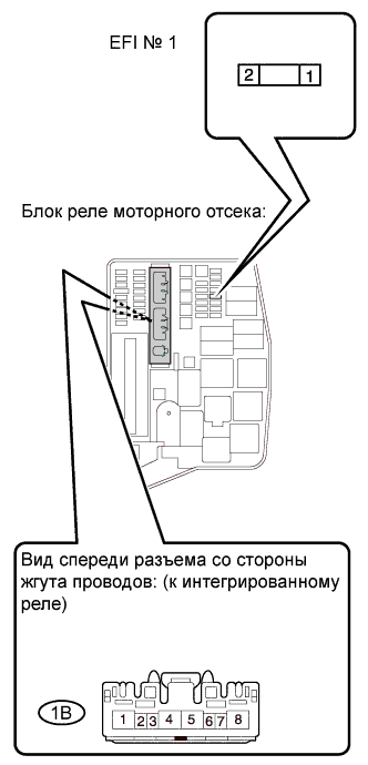
| 6.CHECK HARNESS AND CONNECTOR (INTEGRATION RELAY (EFI MAIN RELAY) - EFI NO. 1 FUSE) |
Remove the integration relay from the engine room relay block.
Disconnect the integration relay connector.
Remove the EFI No. 1 fuse from the engine room relay block.
Measure the resistance according to the value(s) in the table below.
- Standard resistance (Check for open):
Tester Connection
| Condition
| Specified Condition
|
1B-4 - 1 (EFI No. 1 fuse)
| Always
| Below 1 Ω
|
- Standard resistance (Check for short):
Tester Connection
| Condition
| Specified Condition
|
1B-4 or 1 (EFI No. 1 fuse) - Body ground
| Always
| 10 kΩ or higher
|
Reinstall the EFI No. 1 fuse.
Reconnect the integration relay connector.
Reinstall the integration relay.
| | REPAIR OR REPLACE HARNESS OR CONNECTOR (INTEGRATION RELAY (EFI MAIN RELAY) - EFI NO. 1 FUSE) |
|
|
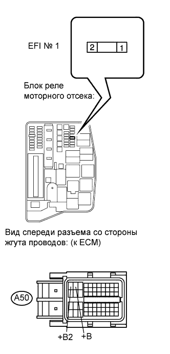
| 7.CHECK HARNESS AND CONNECTOR (EFI NO. 1 FUSE - ECM) |
Disconnect the ECM connector.
Remove the EFI No. 1 fuse from the engine room relay block.
Measure the resistance according to the value(s) in the table below.
- Standard resistance (Check for open):
Tester Connection
| Condition
| Specified Condition
|
2 (EFI No. 1 fuse) - A50-1 (+B2)
| Always
| Below 1 Ω
|
2 (EFI No. 1 fuse) - A50-2 (+B)
| Always
| Below 1 Ω
|
- Standard resistance (Check for short):
Tester Connection
| Condition
| Specified Condition
|
2 (EFI No. 1 fuse) or A50-1 (+B2) - Body ground
| Always
| 10 kΩ or higher
|
2 (EFI No. 1 fuse) or A50-2 (+B) - Body ground
| Always
| 10 kΩ or higher
|
Reinstall the EFI No. 1 fuse.
Reconnect the ECM connector.
| | REPAIR OR REPLACE HARNESS OR CONNECTOR (EFI NO. 1 FUSE - ECM) |
|
|
| 8.CHECK HARNESS AND CONNECTOR (EFI MAIN RELAY - BATTERY) |
Remove the integration relay from the engine room relay block.
Disconnect the integration relay connector.
Disconnect the negative battery terminal.
Disconnect the positive battery terminal.
Measure the resistance according to the value(s) in the table below.
- Standard resistance (Check for open):
Tester Connection
| Condition
| Specified Condition
|
1E-1 - Battery positive terminal
| Always
| Below 1 Ω
|
- Standard resistance (Check for short):
Tester Connection
| Condition
| Specified Condition
|
1E-1 or Battery positive terminal - Body ground
| Always
| 10 kΩ or higher
|
Reconnect the integration relay connector.
Reinstall the integration relay.
Reconnect the positive battery terminal.
Reconnect the negative battery terminal.
| | REPAIR OR REPLACE HARNESS OR CONNECTOR (EFI MAIN RELAY - BATTERY) |
|
|
| 9.CHECK HARNESS AND CONNECTOR (INTEGRATION RELAY (EFI MAIN RELAY) - BODY GROUND) |
Remove the integration relay from the engine room relay block.
Disconnect the integration relay connector.
Measure the resistance according to the value(s) in the table below.
- Standard resistance:
Tester Connection
| Condition
| Specified Condition
|
1B-3 - Body ground
| Always
| Below 1 Ω
|
Reconnect the integration relay connector.
Reinstall the integration relay.
| | REPAIR OR REPLACE HARNESS OR CONNECTOR (INTEGRATION RELAY (EFI MAIN RELAY) - BODY GROUND) |
|
|
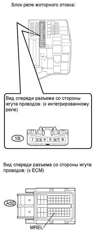
| 10.CHECK HARNESS AND CONNECTOR (INTEGRATION RELAY (EFI MAIN RELAY) - ECM) |
Disconnect the ECM connector.
Remove the integration relay from the engine room relay block.
Disconnect the integration relay connector.
Measure the resistance according to the value(s) in the table below.
- Standard resistance (Check for open):
Tester Connection
| Condition
| Specified Condition
|
1B-2 - A50-44 (MREL)
| Always
| Below 1 Ω
|
- Standard resistance (Check for short):
Tester Connection
| Condition
| Specified Condition
|
1B-2 or A50-44 (MREL) - Body ground
| Always
| 10 kΩ or higher
|
Reconnect the ECM connector.
Reconnect the integration relay connector.
Reinstall the integration relay.
| | REPAIR OR REPLACE HARNESS OR CONNECTOR (INTEGRATION RELAY (EFI MAIN RELAY) - ECM) |
|
|
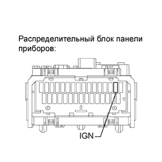
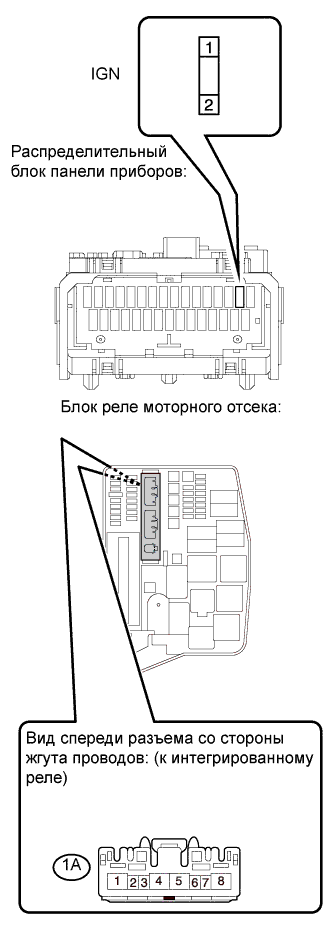
| 11.INSPECT FUSE (IGN FUSE) |
Remove the IGN fuse from the instrument panel junction block.
Measure the resistance according to the value(s) in the table below.
- Standard resistance:
Tester Connection
| Condition
| Specified Condition
|
IGN fuse
| Always
| Below 1 Ω
|
Reinstall the IGN fuse.
| 12.INSPECT FUSE (IG2 FUSE) |
Remove the IG2 fuse from the engine room relay block.
Measure the resistance according to the value(s) in the table below.
- Standard resistance:
Tester Connection
| Condition
| Specified Condition
|
IG2 fuse
| Always
| Below 1 Ω
|
Reinstall the IG2 fuse.
| 13.INSPECT INTEGRATION RELAY (IG2 RELAY) |
Remove the integration relay from the engine room relay block.
Disconnect the integration relay connector.
Measure the IG2 relay resistance.
- Standard resistance:
Tester Connection
| Condition
| Specified Condition
|
1E-1 - 1A-4
| Always
| 10 kΩ or higher
|
Always
| Below 1 Ω
(Apply battery voltage terminal 1A-2 and 1A-3)
|
Reconnect the integration relay connector.
Reinstall the integration relay.
| | REPLACE INTEGRATION RELAY (IG2 RELAY) |
|
|
| 14.CHECK HARNESS AND CONNECTOR (IGN FUSE - ECM) |
Disconnect the ECM connector.
Remove the IGN fuse from the instrument panel junction block.
Measure the resistance according to the value(s) in the table below.
- Standard resistance (Check for open):
Tester Connection
| Condition
| Specified Condition
|
2 (IGN fuse) - A50-28 (IGSW)
| Always
| Below 1 Ω
|
- Standard resistance (Check for short):
Tester Connection
| Condition
| Specified Condition
|
2 (IGN fuse) or A50-28 (IGSW) - Body ground
| Always
| 10 kΩ or higher
|
Reconnect the ECM connector.
Reinstall the IGN fuse.
| | REPAIR OR REPLACE HARNESS OR CONNECTOR (IGN FUSE - ECM) |
|
|
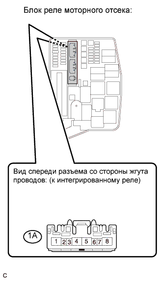
| 15.CHECK HARNESS AND CONNECTOR (INTEGRATION RELAY (IG2 RELAY) - IGN FUSE) |
Remove the integration relay from the engine room relay block.
Disconnect the integration relay connector.
Remove the IGN fuse from the instrument panel junction block.
Measure the resistance according to the value(s) in the table below.
- Standard resistance (Check for open):
Tester Connection
| Condition
| Specified Condition
|
1A-4 - 1 (IGN fuse)
| Always
| Below 1 Ω
|
- Standard resistance (Check for short):
Tester Connection
| Condition
| Specified Condition
|
1A-4 or 1 (IGN fuse) - Body ground
| Always
| 10 kΩ or higher
|
Reconnect the integration relay connector.
Reinstall the integration relay.
Reinstall the IGN fuse.
| | REPAIR OR REPLACE HARNESS OR CONNECTOR (INTEGRATION RELAY (IG2 RELAY) - IGN FUSE) |
|
|
| 16.CHECK HARNESS AND CONNECTOR (INTEGRATION RELAY (IG2 RELAY) - BATTERY) |
Remove the integration relay from the engine room relay block.
Disconnect the integration relay connector.
Disconnect the negative battery terminal.
Disconnect the positive battery terminal.
Measure the resistance according to the value(s) in the table below.
- Standard resistance (Check for open):
Tester Connection
| Condition
| Specified Condition
|
1E-1 - Battery positive terminal
| Always
| Below 1 Ω
|
- Standard resistance (Check for short):
Tester Connection
| Condition
| Specified Condition
|
1E-1 or Battery positive terminal - Body ground
| Always
| 10 kΩ or higher
|
Reconnect the integration relay connector.
Reinstall the integration relay.
Reconnect the positive battery terminal.
Reconnect the negative battery terminal.
| | REPAIR OR REPLACE HARNESS OR CONNECTOR (INTEGRATION RELAY (IG2 RELAY) - BATTERY) |
|
|
| 17.CHECK HARNESS AND CONNECTOR (INTEGRATION RELAY (IG2 RELAY) - BODY GROUND) |
Remove the integration relay from the engine room relay block.
Disconnect the integration relay connector.
Measure the resistance according to the value(s) in the table below.
- Standard resistance:
Tester Connection
| Condition
| Specified Condition
|
1A-3 - Body ground
| Always
| Below 1 Ω
|
Reconnect the integration relay connector.
Reinstall the integration relay.
| | REPAIR OR REPLACE HARNESS OR CONNECTOR (IG2 RELAY - BODY GROUND) |
|
|
| 18.INSPECT FUSE (IG2 NO. 2 FUSE) |
Remove the IG2 No. 2 fuse from the engine room relay block.
Measure the resistance according to the value(s) in the table below.
- Standard resistance:
Tester Connection
| Condition
| Specified Condition
|
IG2 No. 2 fuse
| Always
| Below 1 Ω
|
Reinstall the IG2 No. 2 fuse.
| | REPLACE FUSE (IG2 NO. 2 FUSE) |
|
|
| 19.CHECK HARNESS AND CONNECTOR (IG2 RELAY - IG2 NO. 2 FUSE) |
Remove the integration relay from the engine room relay block.
Disconnect the engine room junction block connector.
Remove the IG2 No. 2 fuse from the engine room relay block.
Measure the resistance according to the value(s) in the table below.
- Standard resistance (Check for open):
Tester Connection
| Condition
| Specified Condition
|
1A-2 - 2 (IG2 No. 2 fuse)
| Always
| Below 1 Ω
|
- Standard resistance (Check for short):
Tester Connection
| Condition
| Specified Condition
|
1A-2 or 2 (IG2 No. 2 fuse) - Body ground
| Always
| 10 kΩ or higher
|
Reconnect the integration relay connector.
Reinstall the engine room junction block.
Reinstall the IG2 No. 2 fuse.
- Result:
Result
| Proceed to
|
OK (w/o Entry and Start System)
| A
|
OK (w/ Entry and Start System)
| B
|
NG
| C
|
| |
|
| | REPAIR OR REPLACE HARNESS OR CONNECTOR (IG2 RELAY - IG2 NO. 2 FUSE) |
|
|
| 20.CHECK HARNESS AND CONNECTOR (IG2 NO. 2 FUSE - IGNITION SWITCH) |
Disconnect the ignition switch connector.
Remove the IG2 No. 2 fuse from the engine room relay block.
Measure the resistance according to the value(s) in the table below.
- Standard resistance (Check for open):
Tester Connection
| Condition
| Specified Condition
|
1 (IG2 No. 2 fuse) - E4-6 (IG2)
| Always
| Below 1 Ω
|
- Standard resistance (Check for short):
Tester Connection
| Condition
| Specified Condition
|
1 (IG2 No. 2 fuse) or E4-6 (IG2) - Body ground
| Always
| 10 kΩ or higher
|
Reconnect the ignition switch connector.
Reinstall the IG2 No. 2 fuse.
| | REPAIR OR REPLACE HARNESS OR CONNECTOR (IG2 NO. 2 FUSE - IGNITION SWITCH) |
|
|
| 21.INSPECT IGNITION SWITCH ASSEMBLY |
Disconnect the ignition switch assembly connector.
Measure the resistance according to the value(s) in the table below.
- Standard resistance:
Tester Connection
| Ignition Switch Position
| Specified Condition
|
All Terminals
| LOCK
| 10 kΩ or higher
|
2 - 4
| ACC
| Below 1 Ω
|
1 - 2 - 4, 5 - 6
| ON
|
1 - 3 - 4, 5 - 6 - 7
| START
|
Reconnect the ignition switch assembly connector.
| 22.INSPECT FUSE (AM2 FUSE) |
Remove the AM2 fuse from the engine room relay block.
Measure the resistance according to the value(s) in the table below.
- Standard resistance:
Tester Connection
| Condition
| Specified Condition
|
AM2 fuse
| Always
| Below 1 Ω
|
Reinstall the AM2 fuse.
| 23.CHECK HARNESS AND CONNECTOR (IGNITION SWITCH - AM2 FUSE) |
Disconnect the ignition switch connector.
Remove the AM2 fuse from the engine room relay block.
Measure the resistance according to the value(s) in the table below.
- Standard resistance (Check for open):
Tester Connection
| Condition
| Specified Condition
|
E4-7 (AM2) - 2 (AM2 fuse)
| Always
| Below 1 Ω
|
- Standard resistance (Check for short):
Tester Connection
| Condition
| Specified Condition
|
E4-7 (AM2) or 2 (AM2 fuse) - Body ground
| Always
| 10 kΩ or higher
|
Reconnect the ignition switch connector.
Reinstall the AM2 fuse.
| | REPAIR OR REPLACE HARNESS OR CONNECTOR (IGNITION SWITCH - AM2 FUSE) |
|
|
| OK |
|
|
|
| REPAIR OR REPLACE HARNESS OR CONNECTOR (AM2 FUSE - BATTERY) |
|
| 24.CHECK HARNESS AND CONNECTOR (IG2 NO. 2 FUSE - MAIN BODY ECU) |
Disconnect the main body ECU connector.
Remove the IG2 No. 2 fuse from the engine room relay block.
Measure the resistance according to the value(s) in the table below.
- Standard resistance (Check for open):
Tester Connection
| Condition
| Specified Condition
|
1 (IG2 No. 2 fuse) - E51-5 (IG2D)
| Always
| Below 1 Ω
|
- Standard resistance (Check for short):
Tester Connection
| Condition
| Specified Condition
|
1 (IG2 No. 2 fuse) or E51-5 (IG2D) - Body ground
| Always
| 10 kΩ or higher
|
Reconnect the main body ECU connector.
Reinstall the IG2 No. 2 fuse.
| | REPAIR OR REPLACE HARNESS OR CONNECTOR (IG2 NO. 2 FUSE - MAIN BODY ECU) |
|
|
| 25.INSPECT FUSE (AM2 NO. 2 FUSE) |
Remove the AM2 No. 2 fuse from the engine room relay block.
Measure the resistance according to the value(s) in the table below.
- Standard resistance:
Tester Connection
| Condition
| Specified Condition
|
AM2 No. 2 fuse
| Always
| Below 1 Ω
|
Reinstall the AM2 No. 2 fuse.
| | REPLACE FUSE (AM2 NO. 2 FUSE) |
|
|
| 26.INSPECT MAIN BODY ECU (AM2 VOLTAGE) |
Disconnect the main body ECU connector.
Measure the voltage according to the value(s) in the table below.
- Standard voltage:
Tester Connection
| Switch Condition
| Specified Condition
|
E50-6 (AM2) - Body ground
| Ignition switch on (IG)
| 9 to 14 V
|
Reconnect the main body ECU connector.
| | REPAIR OR REPLACE HARNESS OR CONNECTOR (BATTERY - MAIN BODY ECU) |
|
|