Система Sfi Цепь Управления Топливным Насосом. Corolla Auris
Двигатель. COROLLA, AURIS. ZZE150 ZRE151,152 NDE150
DESCRIPTION
WIRING DIAGRAM
INSPECTION PROCEDURE
PERFORM ACTIVE TEST USING INTELLIGENT TESTER (OPERATE C/OPN RELAY)
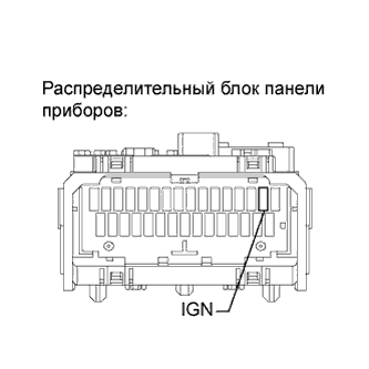
INSPECT FUSE (IGN FUSE)
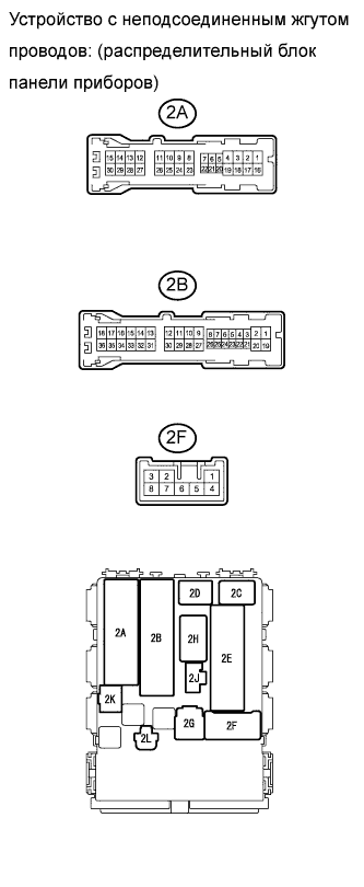
INSPECT INSTRUMENT PANEL JUNCTION BLOCK (C/OPN RELAY)
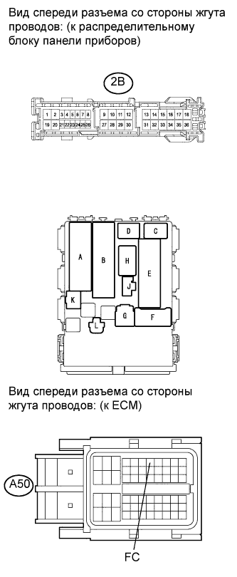
CHECK HARNESS AND CONNECTOR (C/OPN RELAY - ECM)
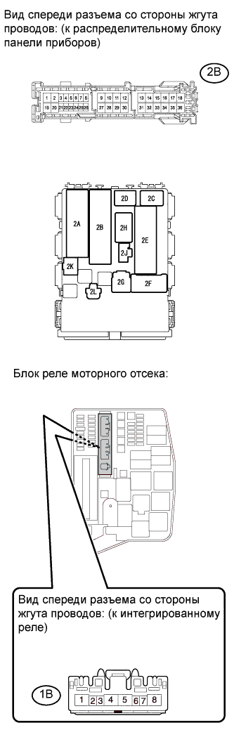
CHECK HARNESS AND CONNECTOR (C/OPN RELAY - INTEGRATION RELAY (EFI MAIN RELAY))
CHECK HARNESS AND CONNECTOR (C/OPN RELAY - FUEL PUMP)
CHECK HARNESS AND CONNECTOR (FUEL PUMP - BODY GROUND)
INSPECT FUEL PUMP
CHECK ECM POWER SOURCE CIRCUIT
СИСТЕМА SFI - Цепь управления топливным насосом |
DESCRIPTION
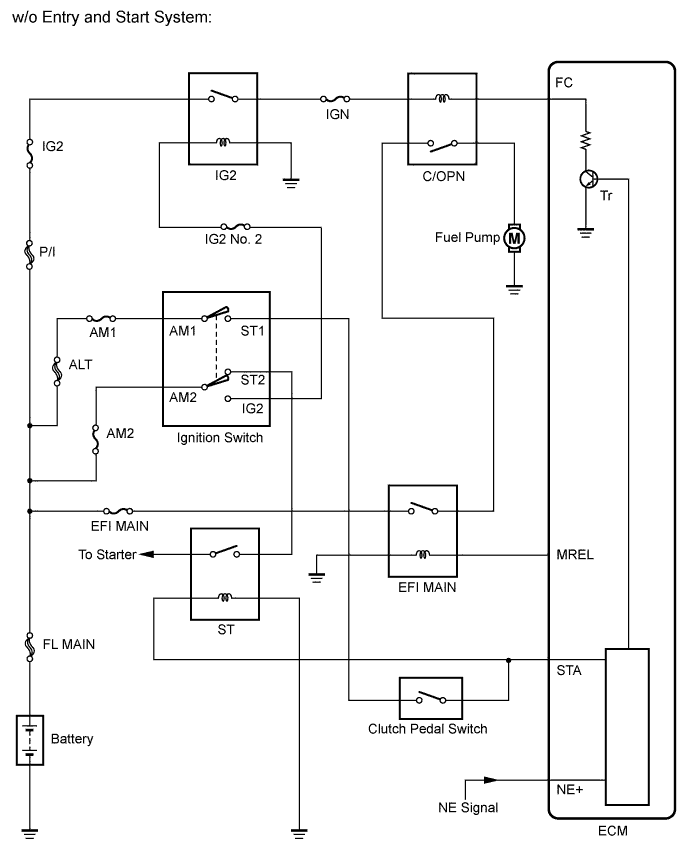
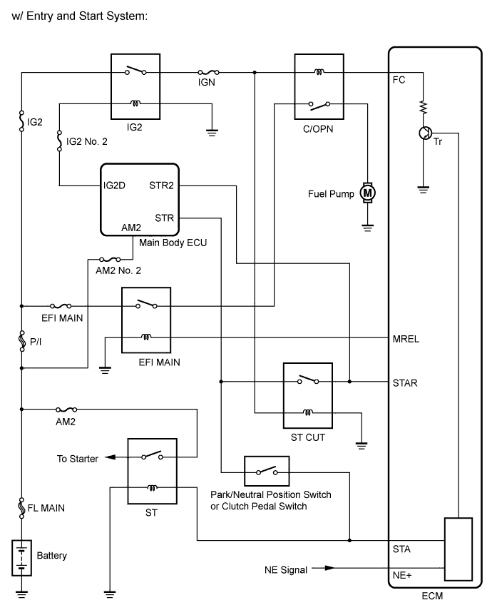
In the diagram below, when the engine is cranked, current flows from terminal ST1 (STR) of the ignition switch (power source control ECU) to the starter relay coil and current also flows to terminal STA of the ECM (STA signal).When the STA signal and NE signal are input to the ECM, Tr is turned ON, current flows to the coil of the circuit opening relay, the relay switches on, power is supplied to the fuel pump and the fuel pump operates.While the NE signal is generated (engine running), the ECM keeps Tr ON (circuit opening relay ON) and the fuel pump also keeps operating.
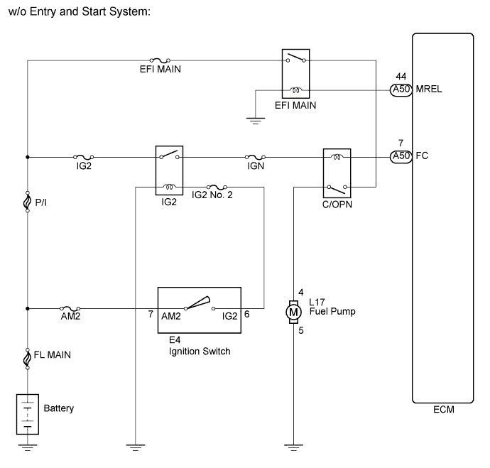
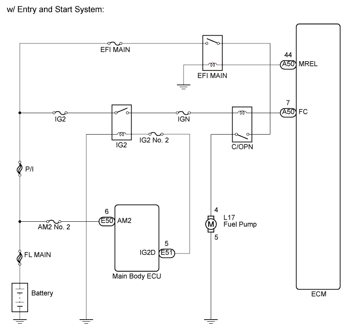
WIRING DIAGRAM
INSPECTION PROCEDURE
| 1.PERFORM ACTIVE TEST USING INTELLIGENT TESTER (OPERATE C/OPN RELAY) |
Connect the intelligent tester to the DLC3.
Turn the ignition switch on (IG).
Turn the tester on.
Select the following menu items: Powertrain / Engine and ECT / Active Test / Control the Fuel Pump / Speed.
Check whether the fuel pump operation sound occurs when performing the Active Test on the tester.
- OK:
- Fuel pump operating sound occurs.
| OK |
|
|
|
| PROCEED TO NEXT CIRCUIT INSPECTION SHOWN IN PROBLEM SYMPTOMS TABLE (Нажмите здесь) |
|
| 2.INSPECT FUSE (IGN FUSE) |
Remove the IGN fuse from the instrument panel junction block.
Measure the resistance according to the value(s) in the table below.
- Standard resistance:
Tester Connection
| Condition
| Specified Condition
|
IGN fuse
| Always
| Below 1 Ω
|
Reinstall the IGN fuse.
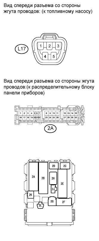
| 3.INSPECT INSTRUMENT PANEL JUNCTION BLOCK (C/OPN RELAY) |
Disconnect the instrument panel junction block connector.
Measure the resistance according to the value(s) in the table below.
- Standard resistance:
Tester Connection
| Condition
| Specified Condition
|
2A-8 - 2B-11
| Always
| 10 kΩ or higher
|
Always
| Below 1 Ω
(Apply battery voltage to terminals 2B-10 and 2F-4)
|
Reconnect the instrument panel junction block connector.
| | REPLACE INSTRUMENT PANEL JUNCTION BLOCK (C/OPN RELAY) |
|
|
| 4.CHECK HARNESS AND CONNECTOR (C/OPN RELAY - ECM) |
Disconnect the ECM connector.
Disconnect the instrument panel junction block connector.
Measure the resistance according to the value(s) in the table below.
- Standard resistance (Check for open):
Tester Connection
| Condition
| Specified Condition
|
2B-10 - A50-7 (FC)
| Always
| Below 1 Ω
|
- Standard resistance (Check for short):
Tester Connection
| Condition
| Specified Condition
|
2B-10 or A50-7 (FC) - Body ground
| Always
| 10 kΩ or higher
|
Reconnect the ECM connector.
Reconnect the instrument panel junction block connector.
| | REPAIR OR REPLACE HARNESS OR CONNECTOR (C/OPN RELAY - ECM) |
|
|
| 5.CHECK HARNESS AND CONNECTOR (C/OPN RELAY - INTEGRATION RELAY (EFI MAIN RELAY)) |
Remove the integration relay from engine room junction block.
Disconnect the integration relay connector.
Disconnect the instrument panel junction block connector.
Measure the resistance according to the value(s) in the table below.
- Standard resistance (Check for open):
Tester Connection
| Condition
| Specified Condition
|
2B-11 - 1B-4
| Always
| Below 1 Ω
|
- Standard resistance (Check for short):
Tester Connection
| Condition
| Specified Condition
|
2B-11 or 1B-4 - Body ground
| Always
| 10 kΩ or higher
|
Reconnect the instrument panel junction block connector.
Reconnect the integration relay connector.
Reinstall the integration relay.
| | REPAIR OR REPLACE HARNESS OR CONNECTOR (C/OPN RELAY - INTEGRATION RELAY (EFI MAIN RELAY)) |
|
|
| 6.CHECK HARNESS AND CONNECTOR (C/OPN RELAY - FUEL PUMP) |
Disconnect the fuel pump connector.
Disconnect the instrument panel junction block connector.
Measure the resistance according to the value(s) in the table below.
- Standard resistance (Check for open):
Tester Connection
| Condition
| Specified Condition
|
2A-8 - L17-4
| Always
| Below 1 Ω
|
- Standard resistance (Check for short):
Tester Connection
| Condition
| Specified Condition
|
2A-8 or L17-4 - Body ground
| Always
| 10 kΩ or higher
|
| | REPAIR OR REPLACE HARNESS OR CONNECTOR (C/OPN RELAY - FUEL PUMP) |
|
|
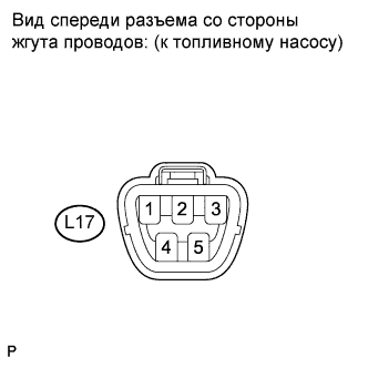
| 7.CHECK HARNESS AND CONNECTOR (FUEL PUMP - BODY GROUND) |
Disconnect the fuel pump connector.
Measure the resistance according to the value(s) in the table below.
- Standard resistance:
Tester Connection
| Condition
| Specified Condition
|
L17-5 - Body ground
| Always
| Below 1 Ω
|
Reconnect the fuel pump connector.
| | REPAIR OR REPLACE HARNESS OR CONNECTOR (FUEL PUMP - BODY GROUND) |
|
|
Inspect the fuel pump (See page Нажмите здесь).
| 9.CHECK ECM POWER SOURCE CIRCUIT |
Check the ECM power source circuit (See page Нажмите здесь).
| | REPAIR OR REPLACE ECM POWER SOURCE CIRCUIT |
|
|