Стартер (Для 1,4 И 2,0 Квт) -- Проверка |
| 1. INSPECT STARTER ASSEMBLY |
- ПРИМЕЧАНИЕ:
- The following tests must be performed for no longer than 5 seconds to prevent the coil from burning out.
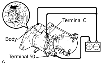
Perform the pull-in test.
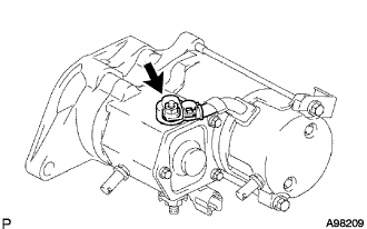
Remove the nut and disconnect the lead wire from terminal C.
Connect the battery to the starter magnetic switch as shown in the illustration. Check that the clutch pinion gear is extended.
If the clutch pinion gear does not move, replace the magnet starter switch assembly.
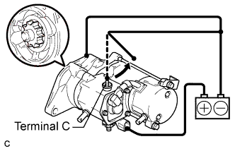
Perform the hold-in test.
Disconnect the negative (-) lead from terminal C. Check that the clutch pinion gear remains extended.
If the clutch pinion gear returns inward, replace the magnet starter switch assembly.
 |
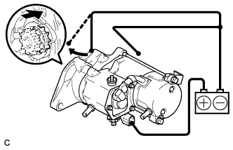
Check the operation.
Disconnect the negative (-) lead from the switch body. Check that the clutch pinion gear returns.
If the clutch pinion gear does not return inward, replace the magnet starter switch assembly.
 |
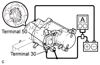
Perform the no-load performance test.
Connect the lead wire to terminal C. Make sure that the lead is not grounded.
- Момент затяжки:
- 5.9 Н*м{60 кгс*см, 52 фунт-сила-дюймов}
Clamp the starter in a vise.
Connect the battery and an ammeter to the starter as shown in the illustration.
Check that the starter rotates smoothly and steadily with the clutch pinion gear extended. Check that the ammeter reads the specified current.
- Standard current:
Tester connection Condition Specified condition Battery positive terminal - Terminal 30 - Terminal 50 11.5 V for 1.4 kW: Below 90A
for 2.0 kW: Below 100 A
|
| 2. INSPECT STARTER YOKE ASSEMBLY |
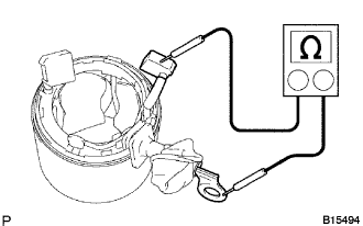
Check the resistance (for 1.4 kW Type).
Using an ohmmeter, measure the resistance between the lead wire and brush lead.
- Standard resistance:
Tester connection Condition Specified condition Lead wire - Brush lead - Below 1 Ω
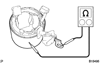
Using an ohmmeter, measure the resistance between the lead wire and body.
- Standard resistance:
Tester connection Condition Specified condition Lead wire - body - 10 kΩ or higher
 |
Check the resistance (for 2.0 kW Type).
Using an ohmmeter, measure the resistance between the lead wire and brush lead.
- Standard resistance:
Tester connection Condition Specified condition Lead wire - Brush lead - Below 1 Ω
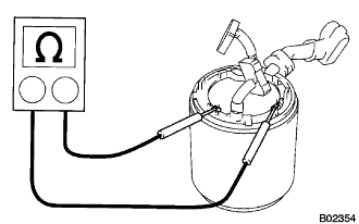
Using an ohmmeter, measure the resistance between the shunt oil terminals.
- Standard resistance:
Tester connection Condition Specified condition shunt oil terminal - shunt oil terminal 20°C (68°F) 1.5 to 1.9 Ω
|
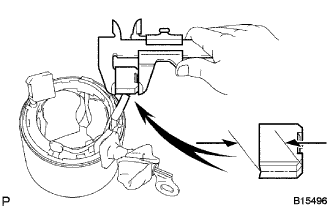
Inspect the brush length.
Using vernier calipers, measure the brush length.
- Standard:
Starter type Standard length Minimum length 1.4 kW 15.5 mm (0.610 in.) 8.5 mm (0.335 in.) 2.0 kW 15.0 mm (0.591 in.) 9.0 mm (0.354 in.)
 |
| 3. INSPECT STARTER ARMATURE ASSEMBLY |
Check the appearance.
Check that there is no deformation or damage to the starter armature assembly.
If there are any defects, replace the starter armature assembly.
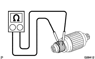
Check the commutator for open circuits.
Using an ohmmeter, measure the resistance between the segments of the commutator.
- Standard resistance:
Tester connection Condition Specified condition Segment - Segment - Below 1 Ω
 |
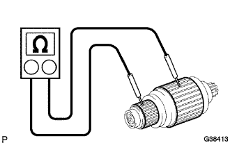
Check the commutator for ground.
Using an ohmmeter, measure the resistance between the commutator and coil core.
- Standard resistance:
Tester connection Condition Specified condition Commutator - Coil core - 10 kΩ or higher
 |
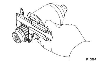
Inspect the diameter.
Using vernier calipers, measure the diameter.
- Standard:
Starter type Standard depth Minimum depth 1.4 kW 30 mm (1.181 in.) 29 mm (1.142 in.) 2.0 kW 35 mm (1.378 in.) 34 mm (1.339 in.)
 |
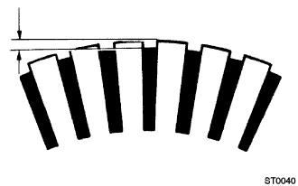
Inspect the depth.
Using vernier calipers, measure the undercut depth.
- Standard:
Starter type Standard depth Minimum depth 1.4 kW 0.6 mm (0.024 in.) 0.2 mm (0.008 in.) 2.0 kW 0.7 mm (0.028 in.) 0.2 mm (0.008 in.)
 |
| 4. INSPECT STARTER BRUSH HOLDER ASSEMBLY |
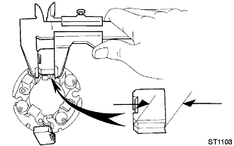
Inspect the brush length.
Using vernier calipers, measure the brush length.
- Standard:
Starter type Standard length Minimum length 1.4 kW 15.5 mm (0.610 in.) 8.5 mm (0.335 in.) 2.0 kW 15.0 mm (0.591 in.) 9.0 mm (0.354 in.)
 |
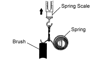
Inspect the brush spring load.
Using a spring scale, measure the load as soon as the spring is detached from the brush.
- Standard:
Starter type Standard load Minimum load 1.4 kW 17.6 to 23.5 N (1.8 to 2.4 kgf, 4.0 to 5.3 lbf) 11.8 N (1.2 kgf, 2.7 lbf) 2.0 kW 21.5 to 27.5 N (2.2 to 2.8 kgf, 4.9 to 6.2 lbf) 12.7 N (1.3 kgf, 2.9 lbf)
 |
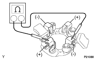
Check the resistance.
Using an ohmmeter, measure the resistance between the positive (+) and negative (-) brush holders.
- Standard resistance:
Tester connection Condition Specified condition Positive brush holder - Negative brush holder - 10 kΩ or higher
 |
| 5. INSPECT MAGNET STARTER SWITCH ASSEMBLY |
Check the resistance.
Using an ohmmeter, measure the resistance between terminals 50 and C.
- Standard resistance:
Tester connection Condition Specified condition Terminal 50 - Terminal C - Below 1 Ω
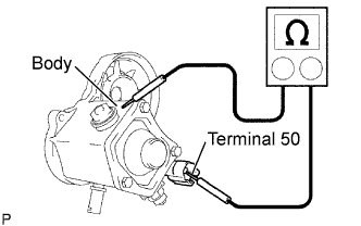
Using an ohmmeter, measure the resistance between terminal 50 and the body.
- Standard resistance:
Tester connection Condition Specified condition Terminal 50 - Body - Below 2 Ω
 |
| 6. INSPECT STARTER CLUTCH SUB-ASSEMBLY |
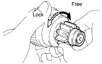
Check the starter clutch.
Rotate the clutch pinion gear clockwise and check that it turns freely. Try to rotate the clutch pinion gear counterclockwise and check that it locks.
If necessary, replace the starter clutch sub-assembly.
 |