CHECK TCM (+B AND GND TERMINALS)
CHECK HARNESS AND CONNECTOR (TCM - ECM)
CHECK HARNESS OR CONNECTOR (TCM - BODY GROUND)
DTC U0100 Lost Communication with ECM/PCM "A" |
DESCRIPTION
The Transmission Control Module (TCM) and ECM perform 2-way communications with each other via the Controller Area Network (CAN). The TCM sends signals to the ECM concerning required engine rpm, required engine torques, warning indicators in the combination meter, DTCs and other data. The ECM sends signals to the TCM concerning engine rpm, opening angles of the throttle valve, temperature of intake air, temperature of engine coolant, engine torques and other data. If the TCM cannot communicate with the ECM, the TCM will conclude that there is a malfunction in the CAN system, illuminate the MIL, Multi-mode Manual Transmission Warning Light and set a DTC.| DTC No. | DTC Detection Condition | Trouble Area |
| U0100 | No communication with the ECM (1-trip detection logic) |
|
WIRING DIAGRAM

INSPECTION PROCEDURE
- УКАЗАНИЕ:
- If the CAN communication malfunctions, the TCM cannot receive the current data from the ECM. In this case, the freeze frame data output from the TCM has not been updated, so it will not be useful information for the inspection procedure. However, reading the Data List as the first step of troubleshooting is effective to find malfunctions.
- ПРИМЕЧАНИЕ:
- In the table below, the values listed under Normal Conditions are for reference only. Do not depend solely on these reference values when deciding whether a part is faulty or not.
- Warm up the engine.
- Turn the ignition switch off.
- Connect the intelligent tester to the DLC3.
- Turn the ignition switch on (IG) and turn the tester ON.
- Following the display on the tester, read the Data List.
| Items [Abbreviation] | Measurement Items: Display | Normal Conditions | Diagnostic Notes |
| Calculated Engine Load [Calc E/G Load] | Calculated load by ECM: Min.: 0 %, Max.: 100 % | 10 to 25 %: Idling 5 to 20 %: Running without load (2,500 rpm) | - |
| Engine Coolant Temperature [Coolant Temp] | Coolant temperature: Min.: -40°C , Max.: 215°C | 75 to 95°C (167 to 203°F): After engine warmed up |
|
| Backup Engine Speed [Bacup Engin Spd] | Back-up engine speed: Min.: 0 rpm, Max.: 8,160 rpm | 0 rpm: Vehicle stopped Approximately same as tachometer reading: Vehicle running | 0 rpm displayed when malfunction in CAN communication |
| Accelerator Pedal Angle [Accel Pedl Angl] | Accelerator pedal angle Min.: 0 %, Max.: 100 % | 0 %: Accelerator pedal released | 0 % displayed when malfunction in CAN communication |
- ПРИМЕЧАНИЕ:
- In ECM replacement, perform the REGISTRATION (Injector compensation codes) after installing the ECM (for 1ND-TV) (See page Нажмите здесь).
| 1.CHECK TCM (+B AND GND TERMINALS) |
Disconnect the TCM connector.
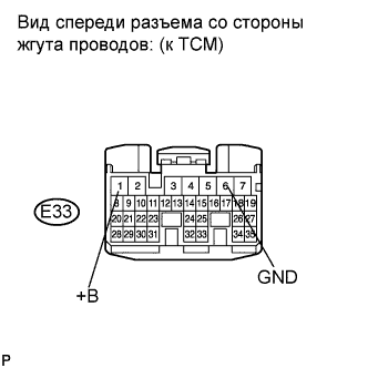 |
Turn the ignition switch on (IG).
Measure the voltage according to the value(s) in the table below.
- Standard voltage:
Tester Connection Switch Condition Specified Condition E33-1 (+B) - E33-6 (GND) Ignition switch on (IG) 11 to 14 V
Turn the ignition switch off.
Reconnect the TCM connector.
|
| ||||
| OK | |
| 2.CHECK HARNESS AND CONNECTOR (TCM - ECM) |
Disconnect the TCM connector.
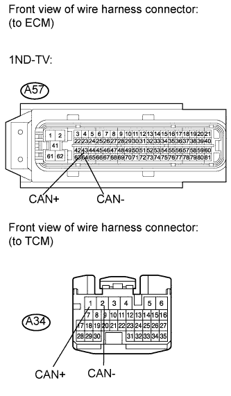 |
Disconnect the ECM connector.
Measure the resistance according to the value(s) in the table below.
- Standard resistance (check for open):
Tester Connection Condition Specified Condition A57-43 (CAN+) - A34-1 (CAN+) Always Below 1 Ω A57-64 (CAN-) - A34-2 (CAN-) ↑ Below 1 Ω
- Standard resistance (check for short):
Tester Connection Condition Specified Condition A57-43 (CAN+) or A34-1 (CAN+) - Body ground Always 10 kΩ or higher A57-64 (CAN-) or A34-2 (CAN-) - Body ground ↑ 10 kΩ or higher
Reconnect the TCM connector.
Reconnect the ECM connector.
|
| ||||
| OK | |
| 3.REPLACE ECM |
Replace the ECM (for 1ND-TV) (See page Нажмите здесь).
- ПРЕДОСТЕРЕЖЕНИЕ:
- Replace the ECM with the ECM of normally functioning vehicle of the same model.
| NEXT | |
| 4.CHECK IF DTC RECURS |
Connect the intelligent tester to the DLC3.
Clear the DTC (See page Нажмите здесь).
Start the engine.
Read the DTCs.
- Result:
Result Proceed to U0100 A No DTC B
|
| ||||
| A | ||
| ||
| 5.CHECK HARNESS OR CONNECTOR (TCM - BODY GROUND) |
Disconnect the TCM connector.
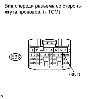 |
Measure the resistance according to the value(s) in the table below.
- Standard resistance:
Tester Connection Condition Specified Condition E33-6 (GND) - Body ground Always Below 1 Ω
Reconnect the TCM connector.
|
| ||||
| OK | |
| 6.INSPECT FUSE (ECU-B2 FUSE) |
Remove the ECU-B2 fuse from the engine room relay block and engine room junction block.
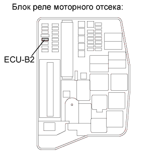 |
Measure the resistance according to the value(s) in the table below.
- Standard resistance:
Tester Connection Condition Specified Condition 1 - 2 Always Below 1 Ω
Reinstall the ECU-B2 fuse.
|
| ||||
| OK | ||
| ||