Dtc P0652 Sensor Reference Voltage B Circuit Low. Corolla Auris
Двигатель. COROLLA, AURIS. ZZE150 ZRE151,152 NDE150
DESCRIPTION
WIRING DIAGRAM
INSPECTION PROCEDURE
CHECK ANY OTHER DTCS OUTPUT (IN ADDITION TO DTC P0652 AND/OR P0653)
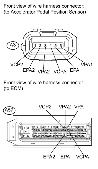
CHECK HARNESS AND CONNECTOR (ACCELERATOR PEDAL POSITION SENSOR - ECM)
INSPECT ECM (VC VOLTAGE)
DTC P0652 Sensor Reference Voltage "B" Circuit Low |
DTC P0653 Sensor Reference Voltage "B" Circuit High |
DESCRIPTION
Refer to DTC P1120 (See page Нажмите здесь).DTC No.
| DTC Detection Condition
| Trouble Area
|
P0652
| Power voltage (5 V as standard) supplied from ECM to accelerator pedal position sensor is lower than threshold
(The MIL is illuminated and a DTC is immediately set when a malfunction is detected)
| - Accelerator pedal position sensor
- Open or short in accelerator pedal position sensor circuit
- ECM
|
P0653
| Power voltage (5 V as standard) supplied from ECM to accelerator pedal position sensor is higher than threshold
(The MIL is illuminated and a DTC is immediately set when a malfunction is detected)
|
- УКАЗАНИЕ:
- These DTCs are set when the ignition switch is in the ON position.
WIRING DIAGRAM
Refer to DTC P1120 (See page Нажмите здесь).
INSPECTION PROCEDURE
| 1.CHECK ANY OTHER DTCS OUTPUT (IN ADDITION TO DTC P0652 AND/OR P0653) |
Connect the intelligent tester to the DLC3.
Turn the ignition switch to the ON position.
Turn the tester on.
Enter the following menu items: Powertrain / Engine and ECT / DTC.
Read the DTCs.
- Result:
Result
| Proceed to
|
DTC P0652 and/or P0653 are output
| A
|
DTC P0652 and/or P0653 and other DTCs are output
| B
|
- УКАЗАНИЕ:
- If any DTCs other than P0652 and/or P0653 are output, troubleshoot those DTCs first.
| 2.CHECK HARNESS AND CONNECTOR (ACCELERATOR PEDAL POSITION SENSOR - ECM) |
Disconnect the accelerator pedal position sensor connector.
Disconnect the ECM connector.
Measure the resistance according to the value(s) in the table below.
- Standard resistance (check for open):
Tester Connection
| Condition
| Specified Condition
|
A3-4 (VCPA) - A57-34 (VCPA)
| Always
| Below 1 Ω
|
A3-6 (VPA1) - A57-15 (VPA)
| Always
| Below 1 Ω
|
A3-5 (EPA) - A57-54 (EPA)
| Always
| Below 1 Ω
|
A3-1 (VCP2) - A57-33 (VCP2)
| Always
| Below 1 Ω
|
A3-3 (VPA2) - A57-14 (VPA2)
| Always
| Below 1 Ω
|
A3-2 (EPA2) - A57-53 (EPA2)
| Always
| Below 1 Ω
|
- Standard resistance (check for short):
Tester Connection
| Condition
| Specified Condition
|
A3-4 (VCPA) or A57-34 (VCPA) - Body ground
| Always
| 10 kΩ or higher
|
A3-6 (VPA1) or A57-15 (VPA) - Body ground
| Always
| 10 kΩ or higher
|
A3-5 (EPA) or A57-54 (EPA) - Body ground
| Always
| 10 kΩ or higher
|
A3-1 (VCP2) or A57-33 (VCP2) - Body ground
| Always
| 10 kΩ or higher
|
A3-3 (VPA2) or A57-14 (VPA2) - Body ground
| Always
| 10 kΩ or higher
|
A3-2 (EPA2) or A57-53 (EPA2) - Body ground
| Always
| 10 kΩ or higher
|
Reconnect the accelerator pedal position sensor connector.
Reconnect the ECM connector.
| | REPAIR OR REPLACE HARNESS OR CONNECTOR (ACCELERATOR PEDAL POSITION SENSOR - ECM) |
|
|
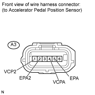
| 3.INSPECT ECM (VC VOLTAGE) |
Disconnect the accelerator pedal position sensor connector.
Turn the ignition switch to the ON position.
Measure the voltage according to the value(s) in the table below.
- Standard voltage:
Tester Connection
| Switch Condition
| Specified Condition
|
A3-1 (VCP2) - A3-2 (EPA2)
| Ignition switch ON
| 4.5 to 5.5 V
|
A3-4 (VCPA) - A3-5 (EPA)
| Ignition switch ON
| 4.5 to 5.5 V
|
Reconnect the accelerator pedal position sensor connector.
| OK |
|
|
|
| REPLACE ACCELERATOR PEDAL ASSEMBLY (ACCELERATOR PEDAL POSITION SENSOR) (Нажмите здесь) |
|