Двигатель. COROLLA, AURIS. ZZE150 ZRE151,152 NDE150
DESCRIPTION
WIRING DIAGRAM
INSPECTION PROCEDURE
CHECK ANY OTHER DTCS OUTPUT (IN ADDITION TO DTC P0400)
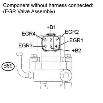
INSPECT EGR VALVE ASSEMBLY
CHECK EGR VALVE ASSEMBLY (VOLTAGE)
CHECK HARNESS AND CONNECTOR (EGR VALVE ASSEMBLY - ECM)
CHECK FOR DEPOSIT (EGR VALVE ASSEMBLY)
CHECK FOR DEPOSIT (EGR PASSAGE)
INSPECT FOR EXHAUST GAS LEAK
INSPECT DIESEL THROTTLE BODY ASSEMBLY
READ VALUE USING INTELLIGENT TESTER (MAF)
INSPECT FUSE (EFI NO. 2 FUSE)
DTC P0400 Exhaust Gas Recirculation Flow |
DESCRIPTION
The EGR (Exhaust Gas Recirculation) system recirculates exhaust gases, which are controlled to the proper volume in accordance with driving conditions. The recirculated gas mingles with the intake air, therefore slowing down the engine combustion and lowering the combustion temperature. This helps reduce nitrogen oxide (NOx) emissions.In order to increase circulatory efficiency, the ECM adjusts the lift of the EGR valve and intake shutter valve (throttle valve).DTC No.
| DTC Detection Condition
| Trouble Area
|
P0400
| Target and actual mass air flow rates differ
(The MIL is illuminated and a DTC is set when the same malfunction is detected on 2 consecutive trips*
*: One trip is counted when the ignition switch is turned from off to the ON position and back to off)
| - Open or short in EGR circuit
- EGR valve assembly
- EGR passage
- Intake shutter
- Mass air flow meter
- Contamination in mass air flow meter
- ECM
|
- УКАЗАНИЕ:
- DTC P0400 is set while the engine is running in steady condition.
- If DTC P0403 has already been set, P0400 is not set.
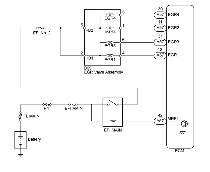
WIRING DIAGRAM
Refer to DTC P0121 (See page Нажмите здесь).
INSPECTION PROCEDURE
- УКАЗАНИЕ:
- Read freeze frame data using an intelligent tester. The ECM records vehicle and driving condition information as freeze frame data the moment a DTC is stored. When troubleshooting, freeze frame data can be helpful in determining whether the vehicle was running or stopped, whether the engine was warmed up or not, whether the air fuel ratio was lean or rich, as well as other data recorded at the time of a malfunction.
| 1.CHECK ANY OTHER DTCS OUTPUT (IN ADDITION TO DTC P0400) |
Connect the intelligent tester to the DLC3.
Turn the ignition switch to the ON position.
Turn the tester on.
Enter the following menu items: Powertrain / Engine and ECT / DTC.
Read the DTCs.
- Result:
Result
| Proceed to
|
DTC P0400 is output
| A
|
DTC P0400 and other DTCs are output
| B
|
- УКАЗАНИЕ:
- If any DTCs other than P0400 are output, troubleshoot those DTCs first.
| 2.INSPECT EGR VALVE ASSEMBLY |
Disconnect the EGR valve assembly connector.
Measure the resistance according to the value(s) in the table below.
- Standard resistance:
Tester Connection
| Condition
| Specified Condition
|
B69-5 (+B2) - B69-4 (EGR1)
| 20°C (68°F)
| 18.2 to 21.0 Ω
|
B69-5 (+B2) - B69-6 (EGR3)
| 20°C (68°F)
| 18.2 to 21.0 Ω
|
B69-2 (+B1) - B69-1 (EGR2)
| 20°C (68°F)
| 18.2 to 21.0 Ω
|
B69-2 (+B1) - B69-3 (EGR4)
| 20°C (68°F)
| 18.2 to 21.0 Ω
|
Reconnect the EGR valve assembly assembly.
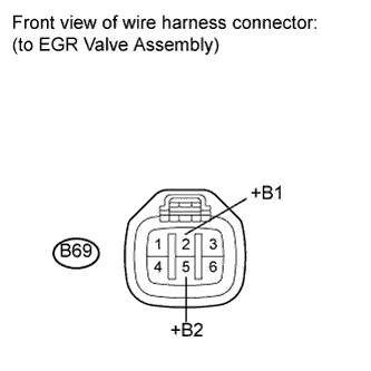
| 3.CHECK EGR VALVE ASSEMBLY (VOLTAGE) |
Disconnect the EGR valve assembly connector.
Turn the ignition switch to the ON position.
Measure the voltage according to the value(s) in the table below.
- Standard voltage:
Tester Connection
| Switch Condition
| Specified Condition
|
B69-2 (+B1) - Body ground
| Ignition switch ON
| 9 to 14 V
|
B69-5 (+B2) - Body ground
| Ignition switch ON
| 9 to 14 V
|
Reconnect the EGR valve assembly connector.
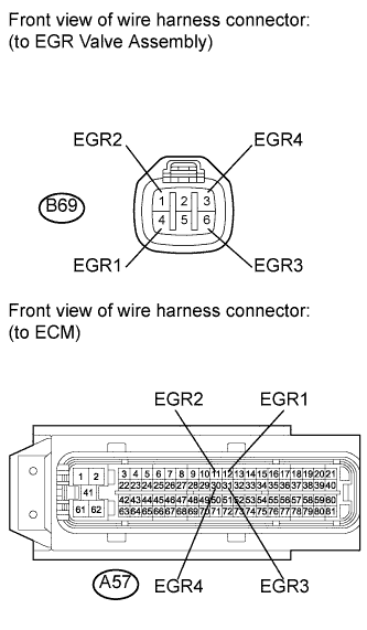
| 4.CHECK HARNESS AND CONNECTOR (EGR VALVE ASSEMBLY - ECM) |
Disconnect the EGR valve assembly connector.
Disconnect the ECM connector.
Measure the resistance according to the value(s) in the table below.
- Standard resistance (Check for open):
Tester Connection
| Condition
| Specified Condition
|
B69-4 (EGR1) - A57-12 (EGR1)
| Always
| Below 1 Ω
|
B69-1 (EGR2) - A57-11 (EGR2)
| Always
| Below 1 Ω
|
B69-6 (EGR3) - A57-31 (EGR3)
| Always
| Below 1 Ω
|
B69-3 (EGR4) - A57-30 (EGR4)
| Always
| Below 1 Ω
|
- Standard resistance (Check for short):
Tester Connection
| Condition
| Specified Condition
|
B69-4 (EGR1) or A57-12 (EGR1) - Body ground
| Always
| 10 kΩ or higher
|
B69-1 (EGR2) or A57-11 (EGR2) - Body ground
| Always
| 10 kΩ or higher
|
B69-6 (EGR3) or A57-31 (EGR3) - Body ground
| Always
| 10 kΩ or higher
|
B69-3 (EGR4) or A57-30 (EGR4) - Body ground
| Always
| 10 kΩ or higher
|
Reconnect the EGR valve assembly connector.
Reconnect the ECM connector.
| | REPAIR OR REPLACE HARNESS OR CONNECTOR (EGR VALVE ASSEMBLY - ECM) |
|
|
| 5.CHECK FOR DEPOSIT (EGR VALVE ASSEMBLY) |
- OK:
- No deposit
| 6.CHECK FOR DEPOSIT (EGR PASSAGE) |
- OK:
- No deposit
| | REPAIR OR REPLACE MALFUNCTIONING PARTS |
|
|
| 7.INSPECT FOR EXHAUST GAS LEAK |
Check for exhaust gas leaks (See page Нажмите здесь).
- OK:
- No leakage
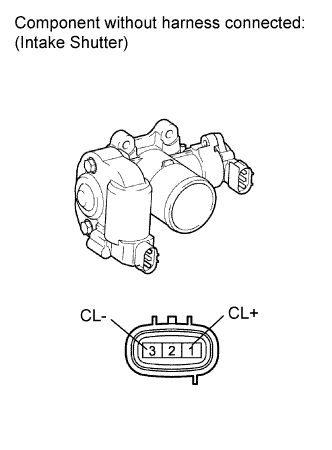
| 8.INSPECT DIESEL THROTTLE BODY ASSEMBLY |
Disconnect the diesel throttle body assembly connector.
Measure the resistance according to the value(s) in the table below.
- Standard resistance:
Tester Connection
| Condition
| Specified Condition
|
1 (CL+) - 3 (CL-)
| 20°C (68°F)
| 0.3 to 100 Ω
|
Reconnect the diesel throttle body assembly connector.
| 9.READ VALUE USING INTELLIGENT TESTER (MAF) |
- ПРИМЕЧАНИЕ:
- Perform the inspection with the vehicle indoors and on a level surface.
- Perform the inspection of the mass air flow meter while it is installed to the air cleaner case (installed to the vehicle).
- During the test, do not use the exhaust air duct to perform suction on the exhaust pipe.
Turn the ignition switch to the ON position.
- ПРИМЕЧАНИЕ:
- Do not run the engine.
Turn the tester on.
Enter the following menu items: Powertrain / Engine and ECT / Data List / MAF.
Wait 30 seconds, and read the values on the tester.
- Standard:
- Less than 0.23 g/sec.
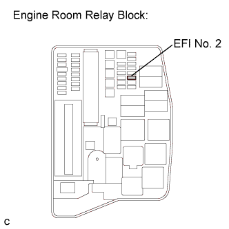
| 10.INSPECT FUSE (EFI NO. 2 FUSE) |
Remove the EFI No. 2 fuse from the engine room relay block.
Measure the resistance according to the value(s) in the table below.
- Standard resistance:
Tester Connection
| Condition
| Specified Condition
|
EFI No. 2 fuse
| Always
| Below 1 Ω
|
Reinstall the EFI No. 2 fuse.
| | REPLACE FUSE (EFI NO. 2 FUSE) |
|
|
| OK |
|
|
|
| REPAIR OR REPLACE HARNESS OR CONNECTOR (EGR VALVE ASSEMBLY - INTEGRATION RELAY (EFI MAIN RELAY)) |
|