Dtc P1120 Accelerator Pedal Position Sensor Circuit Malfunction. Corolla Auris
Двигатель. COROLLA, AURIS. ZZE150 ZRE151,152 NDE150
DESCRIPTION
WIRING DIAGRAM
INSPECTION PROCEDURE
READ VALUE USING INTELLIGENT TESTER (ACCEL POSITION)
CHECK HARNESS AND CONNECTOR (ACCELERATOR PEDAL POSITION SENSOR - ECM)
INSPECT ECM (VC VOLTAGE)
DTC P1120 Accelerator Pedal Position Sensor Circuit Malfunction |
- УКАЗАНИЕ:
- This is the repair procedure for the accelerator pedal position sensor.
- This electrical throttle system does not use a throttle cable.
- This accelerator pedal position sensor is a non-contact type.
DESCRIPTION
The accelerator pedal position sensor is mounted on the accelerator pedal and detects the opening angle of the accelerator pedal. Since this sensor is electronically controlled with Hall-effect elements, accurate control and reliability can be obtained. It has 2 sensors to detect the accelerator position and malfunctions of the accelerator position sensor.In the accelerator pedal position sensor, the voltage applied to pedal terminals VPA and VPA2 of the ECM changes between 0 V and 5 V in proportion to the opening angle of the accelerator pedal. The VPA is a signal which indicates the actual accelerator pedal opening angle and is used for engine control, and the VPA2 is a signal which indicates the information about the opening angle and is used for detecting malfunctions. The ECM judges the current opening angle of the accelerator pedal using signals from terminals VPA and VPA2, and the ECM controls the throttle motor based on these signals.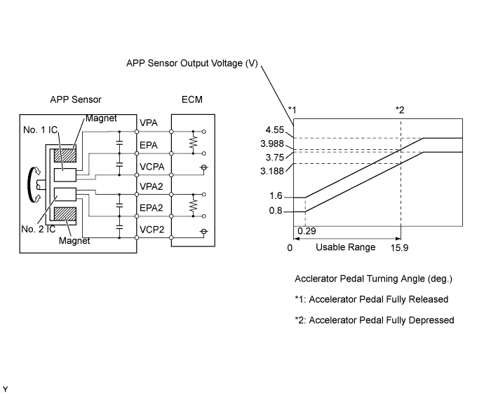
DTC No.
| DTC Detection Condition
| Trouble Area
|
P1120
| Condition (a) or (b) continues for 0.5 seconds or more:
- (a) VPA is less than 0.2 V when accelerator pedal is fully released, or VPA is more than 4.8 V
(The MIL is illuminated and a DTC is immediately set when a malfunction is detected)
- (b) VPA2 is less than 0.5 V when accelerator pedal is fully released, or VPA2 is more than 4.8 V
(The MIL is illuminated and a DTC is immediately set when a malfunction is detected)
| - Open or short in accelerator pedal position sensor circuit
- Accelerator pedal position sensor
- ECM
|
- УКАЗАНИЕ:
- This DTC is set when the ignition switch is in the ON position.
- УКАЗАНИЕ:
- When DTC P1120 is set, check the accelerator pedal position sensor output voltage by selecting the following menu items on the intelligent tester: Powertrain / Engine and ECT / Data List / Accel Position.
- Reference:
Accelerator Pedal Position (Fully Closed)
| Accelerator Pedal Position (Fully Open)
| Trouble Area
|
0 %
| 0 %
| - Open in VCPA or VCP2 circuit
- Open or short in VPA or VPA2 circuit
|
Approximately 100 %
| Approximately 100 %
| - Open in EPA or EPA2 circuit
|
- УКАЗАНИЕ:
- Accelerator pedal positions are expressed as voltages.
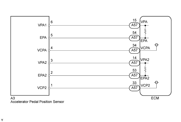
WIRING DIAGRAM
INSPECTION PROCEDURE
Read freeze frame data using an intelligent tester. The ECM records vehicle and driving condition information as freeze frame data the moment a DTC is stored. When troubleshooting, freeze frame data can be helpful in determining whether the vehicle was running or stopped, whether the engine was warmed up or not, whether the air fuel ratio was lean or rich, as well as other data recorded at the time of a malfunction.
| 1.READ VALUE USING INTELLIGENT TESTER (ACCEL POSITION) |
Connect the intelligent tester to the DLC3.
Turn the ignition switch to the ON position.
Turn the tester on.
Enter the following menu items: Powertrain / Engine and ECT / Data List / Accel Position.
Read the values.
- Standard:
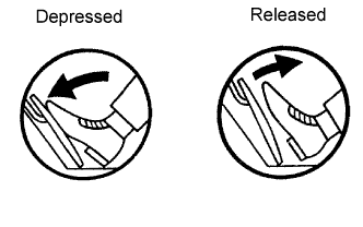
Accelerator Pedal Operation
| Specified Condition
|
Depressed
| 100 %
|
Released
| 0 %
|
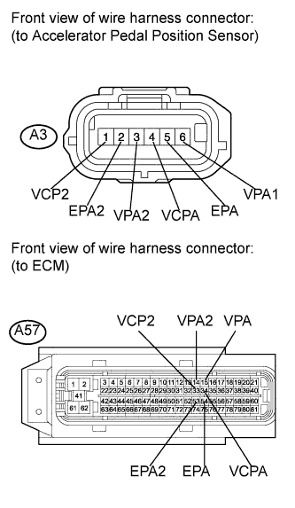
| 2.CHECK HARNESS AND CONNECTOR (ACCELERATOR PEDAL POSITION SENSOR - ECM) |
Disconnect the accelerator pedal position sensor connector.
Disconnect the ECM connector.
Measure the resistance according to the value(s) in the table below.
- Standard resistance (check for open):
Tester Connection
| Condition
| Specified Condition
|
A3-4 (VCPA) - A57-34 (VCPA)
| Always
| Below 1 Ω
|
A3-6 (VPA1) - A57-15 (VPA)
| Always
| Below 1 Ω
|
A3-5 (EPA) - A57-54 (EPA)
| Always
| Below 1 Ω
|
A3-1 (VCP2) - A57-33 (VCP2)
| Always
| Below 1 Ω
|
A3-3 (VPA2) - A57-14 (VPA2)
| Always
| Below 1 Ω
|
A3-2 (EPA2) - A57-53 (EPA2)
| Always
| Below 1 Ω
|
- Standard resistance (check for short):
Tester Connection
| Condition
| Specified Condition
|
A3-4 (VCPA) or A57-34 (VCPA) - Body ground
| Always
| 10 kΩ or higher
|
A3-6 (VPA1) or A57-15 (VPA) - Body ground
| Always
| 10 kΩ or higher
|
A3-5 (EPA) or A57-54 (EPA) - Body ground
| Always
| 10 kΩ or higher
|
A3-1 (VCP2) or A57-33 (VCP2) - Body ground
| Always
| 10 kΩ or higher
|
A3-3 (VPA2) or A57-14 (VPA2) - Body ground
| Always
| 10 kΩ or higher
|
A3-2 (EPA2) or A57-53 (EPA2) - Body ground
| Always
| 10 kΩ or higher
|
Reconnect the accelerator pedal position sensor connector.
Reconnect the ECM connector.
| | REPAIR OR REPLACE HARNESS OR CONNECTOR (ACCELERATOR PEDAL POSITION SENSOR - ECM) |
|
|
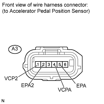
| 3.INSPECT ECM (VC VOLTAGE) |
Disconnect the accelerator pedal position sensor connector.
Turn the ignition switch to the ON position.
Measure the voltage according to the value(s) in the table below.
- Standard voltage:
Tester Connection
| Switch Condition
| Specified Condition
|
A3-1 (VCP2) - A3-2 (EPA2)
| Ignition switch ON
| 4.5 to 5.5 V
|
A3-4 (VCPA) - A3-5 (EPA)
| Ignition switch ON
| 4.5 to 5.5 V
|
Reconnect the accelerator pedal position sensor connector.
| OK |
|
|
|
| REPLACE ACCELERATOR PEDAL ASSEMBLY (ACCELERATOR PEDAL POSITION SENSOR) (Нажмите здесь) |
|