Двигатель. COROLLA, AURIS. ZZE150 ZRE151,152 NDE150
Система Управления Двигателем 1Nd-Tv. COROLLA, AURIS. ZZE150 ZRE151,152 NDE150
READ OUTPUT DTC (DTC P0201, P0202, P0203, P0204 AND/OR P2146)
CHECK HARNESS AND CONNECTOR (ECM - INJECTOR ASSEMBLY)
DTC P0201 Injector Circuit / Open - (Cylinder 1) |
DTC P0202 Injector Circuit / Open - (Cylinder 2) |
DTC P0203 Injector Circuit / Open - (Cylinder 3) |
DTC P0204 Injector Circuit / Open - (Cylinder 4) |
DTC P2146 Fuel Injector Group "A" Supply Voltage Circuit / Open |
DESCRIPTION
The injectors are installed in the cylinder head, and inject fuel into the cylinders based on the signals from the ECM.- УКАЗАНИЕ:
- Injector driver is in the ECM.
| DTC No. | DTC Detection Condition | Trouble Area |
| P0201 | Open or short in injector circuit (cylinder No. 1) for 0.5 seconds or more (The MIL is illuminated and a DTC is immediately set when a malfunction is detected) |
|
| P0202 | Open or short in injector circuit (cylinder No. 2) for 0.5 seconds or more (The MIL is illuminated and a DTC is immediately set when a malfunction is detected) |
|
| P0203 | Open or short in injector circuit (cylinder No. 3) for 0.5 seconds or more (The MIL is illuminated and a DTC is immediately set when a malfunction is detected) |
|
| P0204 | Open or short in injector circuit (cylinder No. 4) for 0.5 seconds or more (The MIL is illuminated and a DTC is immediately set when a malfunction is detected) |
|
| P2146 |
|
|
- УКАЗАНИЕ:
- These DTCs are set when the engine idles for approximately 15 seconds.
- If DTC P0201 is displayed, check the No. 1 injector circuit.
- If DTC P0202 is displayed, check the No. 2 injector circuit.
- If DTC P0203 is displayed, check the No. 3 injector circuit.
- If DTC P0204 is displayed, check the No. 4 injector circuit.
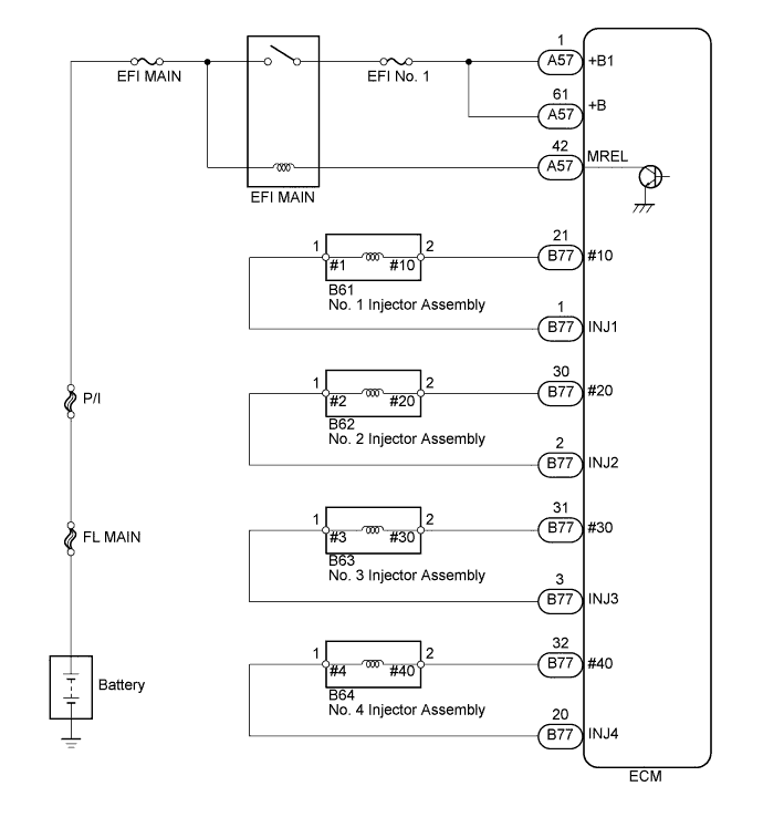
WIRING DIAGRAM
INSPECTION PROCEDURE
- УКАЗАНИЕ:
- Read freeze frame data using an intelligent tester. The ECM records vehicle and driving condition information as freeze frame data the moment a DTC is stored. When troubleshooting, freeze frame data can be helpful in determining whether the vehicle was running or stopped, whether the engine was warmed up or not, whether the air fuel ratio was lean or rich, as well as other data recorded at the time of a malfunction.
| 1.READ OUTPUT DTC (DTC P0201, P0202, P0203, P0204 AND/OR P2146) |
Connect the intelligent tester to the DLC3.
Turn the ignition switch to the ON position.
Turn the tester on.
Enter the following menu items: Powertrain / Engine and ECT / DTC.
Read the DTCs.
- Result:
Result Proceed to DTC P0201, P0202, P0203 and/or P0204, and P2146 are output A DTC only P2146 is output B
|
| ||||
| A | |
| 2.INSPECT INJECTOR ASSEMBLY |
Disconnect the injector assembly connectors.
 |
Measure the resistance according to the value(s) in the table below.
- Standard resistance:
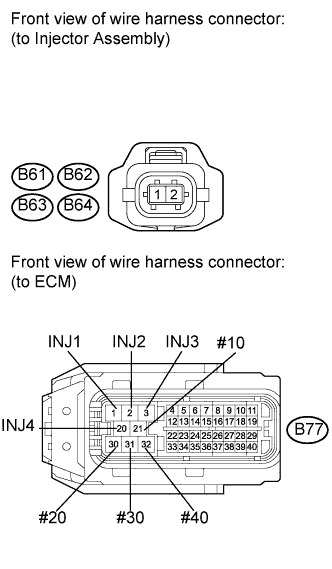
Tester Connection Condition Specified Condition B61-1 - B61-2 20°C (68°F) 0.215 to 0.295 Ω B62-1 - B62-2 20°C (68°F) 0.215 to 0.295 Ω B63-1 - B63-2 20°C (68°F) 0.215 to 0.295 Ω B64-1 - B64-2 20°C (68°F) 0.215 to 0.295 Ω
Reconnect the injector assembly connector.
|
| ||||
| OK | |
| 3.CHECK HARNESS AND CONNECTOR (ECM - INJECTOR ASSEMBLY) |
Disconnect the injector assembly connectors.
 |
Disconnect the ECM connector.
Measure the resistance according to the value(s) in the table below.
- Standard resistance (Check for open):
Tester Connection Condition Specified Condition B77-21 (#10) - B61-2 Always Below 1 Ω B77-30 (#20) - B62-2 Always Below 1 Ω B77-31 (#30) - B63-2 Always Below 1 Ω B77-32 (#40) - B64-2 Always Below 1 Ω B77-1 (INJ1) - B61-1 Always Below 1 Ω B77-2 (INJ2) - B62-1 Always Below 1 Ω B77-3 (INJ3) - B63-1 Always Below 1 Ω B77-20 (INJ4) - B64-1 Always Below 1 Ω
- Standard resistance (Check for short):
Tester Connection Conditions Specified Condition B77-21 (#10) or B61-2 - Body ground Always 10 kΩ or higher B77-30 (#20) or B62-2 - Body ground Always 10 kΩ or higher B77-31 (#30) or B63-2 - Body ground Always 10 kΩ or higher B77-32 (#40) or B64-2 - Body ground Always 10 kΩ or higher B77-1 (INJ1) or B61-1 - Body ground Always 10 kΩ or higher B77-2 (INJ2) or B62-1 - Body ground Always 10 kΩ or higher B77-3 (INJ3) or B63-1 - Body ground Always 10 kΩ or higher B77-20 (INJ4) or B64-1 - Body ground Always 10 kΩ or higher
Reconnect the injector assembly connectors.
Reconnect the ECM connector.
|
| ||||
| OK | ||
| ||