Головка Блока Цилиндров -- Проверка |
| 1. INSPECT CYLINDER HEAD SUB-ASSEMBLY |
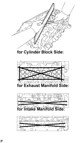
Using a precision straightedge and feeler gauge, measure the warpage of the contact surface of the cylinder block and manifolds.
- Maximum warpage:
- 0.05 mm (0.0020 in.)
 |
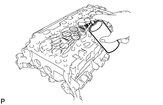
| 2. INSPECT CYLINDER HEAD FOR CRACKS |
Using a dye penetrant, check the intake ports, exhaust ports and cylinder surface for cracks.
If cracked, replace the cylinder head.
 |
| 3. INSPECT CAMSHAFT OIL CLEARANCE |
Clean the bearing caps and camshaft journals.
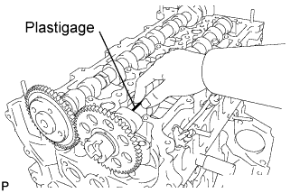 |
Place the camshafts on the cylinder head.
Lay a strip of Plastigage across each of the camshaft journals.
Install the bearing caps (see page Нажмите здесь).
- ПРИМЕЧАНИЕ:
- Do not turn the camshaft.
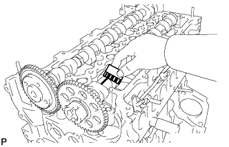
Remove the bearing caps (see page Нажмите здесь).
Measure the Plastigage at its widest point.
- Standard journal clearance:
- 0.025 to 0.062 mm (0.0010 to 0.0024 in.)
- Maximum oil clearance:
- 0.062 mm (0.0024 in.)
 |
Completely remove the Plastigage.
| 4. INSPECT CAMSHAFT THRUST CLEARANCE |
Install the No. 2 camshaft and No. 1 camshaft (see page Нажмите здесь).
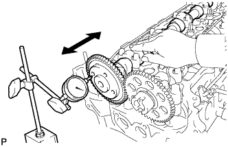 |
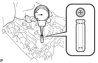
Using a dial indicator, measure the thrust clearance while moving the camshaft back and forth.
- Standard thrust clearance:
- 0.035 to 0.160 mm (0.0014 to 0.0063 in.)
- Maximum thrust clearance:
- 0.160 mm (0.0063 in.)
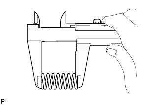
| 5. INSPECT COMPRESSION SPRING |
Using vernier calipers, measure the free length of the compression spring.
- Standard free length:
- 45.90 mm (1.8071 in.)
 |
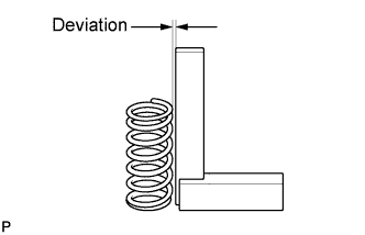
Using a steel square, measure the deviation of the inner compression spring.
- Maximum deviation:
- 1.5 mm (0.059 in.)
- Maximum angle (reference):
- 2°
 |
| 6. INSPECT INTAKE VALVE SEAT |
Apply a light coat of Prussian blue to the valve face.
Lightly press the valve face against the valve seat.
- УКАЗАНИЕ:
- Do not rotate the valve while pressing the valve.
Check the valve face and valve seat.
Check that the contact surfaces of the valve seat and valve face are in the middle area of their respective surfaces, with the width between 1.0 and 1.4 mm (0.039 and 0.055 in.).
If not, correct the valve seat.Check that the contact surfaces of the valve seat and valve face are even around the entire valve seat.
If not, correct the valve seat.
 |
| 7. INSPECT EXHAUST VALVE SEAT |
Apply a light coat of Prussian blue to the valve face.
Lightly press the valve face against the valve seat.
- УКАЗАНИЕ:
- Do not rotate the valve while pressing the valve.
Check the valve face and valve seat.
Check that the contact surfaces of the valve seat and valve face are in the middle area of their respective surfaces, with the width between 1.0 and 1.4 mm (0.039 and 0.055 in.).
If not, correct the valve seat.Check that the contact surfaces of the valve seat and valve face are even around the entire valve seat.
If not, correct the valve seat.
 |
| 8. INSPECT INTAKE VALVE |
Using a gasket scraper, chip off any carbon from the valve head.
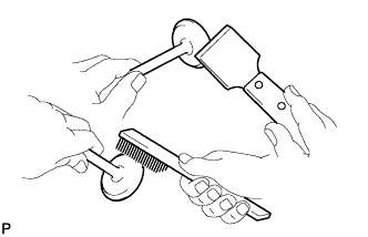 |
Using a wire brush, thoroughly clean the valve.
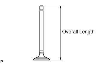
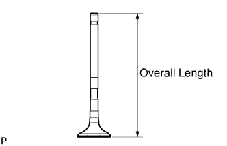
Using vernier calipers, measure the valve's overall length.
- Standard overall length:
- 104.4 mm (4.110 in.)
- Minimum overall length:
- 104.1 mm (4.098 in.)
 |
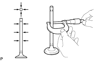
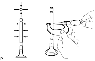
Using a micrometer, measure the diameter of the valve stem.
- Standard valve stem diameter:
- 5.970 to 5.985 mm (0.2350 to 0.2356 in.)
 |
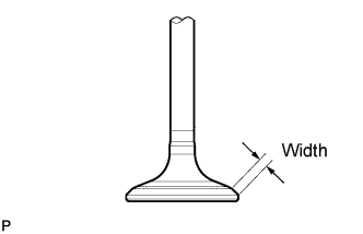
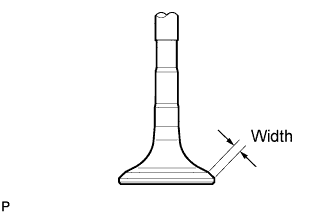
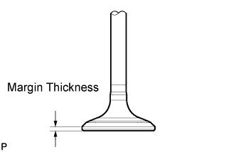
Using vernier calipers, measure the valve head margin thickness.
- Standard margin thickness:
- 1.40 to 1.60 mm (0.055 to 0.063 in.)
- Minimum margin thickness:
- 0.50 mm (0.0197 in.)
 |
| 9. INSPECT EXHAUST VALVE |
Using a gasket scraper, chip off any carbon from the valve head.
|
Using a wire brush, thoroughly clean the valve.
Using vernier calipers, measure the valve's overall length.
- Standard overall length:
- 104.1 mm (4.098 in.)
- Minimum overall length:
- 103.8 mm (4.087 in.)
 |
Using a micrometer, measure the diameter of the valve stem.
- Standard valve stem diameter:
- 5.960 to 5.975 mm (0.2347 to 0.2352 in.)
 |
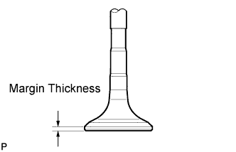
Using vernier calipers, measure the valve head margin thickness.
- Standard margin thickness:
- 1.36 to 1.56 mm (0.0535 to 0.0614 in.)
- Minimum margin thickness:
- 0.50 mm (0.0197 in.)
 |
| 10. INSPECT VALVE GUIDE BUSH |
Using a caliper gauge, measure the inside diameter of the guide bush.
- Bush inside diameter:
- 6.010 to 6.030 mm (0.2366 to 0.2374 in.)
 |
Subtract the valve stem diameter measurement from the guide bush inside diameter measurement.
- Standard oil clearance:
Item Specified value Intake 0.025 to 0.060 mm (0.0010 to 0.0024 in.) Exhaust 0.035 to 0.070 mm (0.0014 to 0.0028 in.)
- Maximum oil clearance:
Item Specified value Intake 0.06 mm (0.0024 in.) Exhaust 0.07 mm (0.0028 in.)
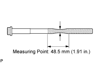
| 11. INSPECT CYLINDER HEAD SET BOLT |
Using vernier calipers, measure the minimum diameter of the elongated thread at the measuring point.
- Standard outside diameter:
- 11.8 to 12.0 mm (0.465 to 0.472 in.)
- Minimum outside diameter:
- 11.20 mm (0.4409 in.)
 |