Трос Механизма Переключения Передач (Для Моделей С Кузовом Типа Хэтчбэк) Установка. Corolla ZZE150
INSTALL TRANSMISSION CONTROL CABLE ASSEMBLY
ADJUST TRANSMISSION CONTROL SELECT CABLE
INSTALL LOWER NO. 1 INSTRUMENT PANEL FINISH PANEL
INSTALL LOWER NO. 2 INSTRUMENT PANEL FINISH PANEL
INSTALL INSTRUMENT PANEL UNDER TRAY
INSTALL FRONT NO. 1 CONSOLE BOX INSERT
INSTALL FRONT NO. 2 CONSOLE BOX INSERT
INSTALL REAR CONSOLE BOX ASSEMBLY (w/o Console Box Lid)
INSTALL REAR CONSOLE BOX ASSEMBLY (w/ Console Box Lid)
INSTALL CONSOLE BOX CARPET (w/o Console Box Lid)
INSTALL CONSOLE BOX CARPET (w/ Console Box Lid)
INSTALL LOWER CENTER INSTRUMENT PANEL FINISH PANEL
INSTALL UPPER CONSOLE PANEL
INSTALL REAR CONSOLE BOX COVER
INSTALL SHIFT LEVER KNOB SUB-ASSEMBLY
INSTALL INSTRUMENT PANEL FINISH PANEL END LH
INSTALL INSTRUMENT PANEL FINISH PANEL END RH
INSTALL NO. 1 FRONT FLOOR HEAT INSULATOR
INSTALL FRONT EXHAUST PIPE ASSEMBLY (for 2ZR-FE)
CONNECT HEATED OXYGEN SENSOR
INSTALL AIR CLEANER CASE SUB-ASSEMBLY (for 2ZR-FE)
INSTALL AIR CLEANER CAP SUB-ASSEMBLY (for 2ZR-FE)
INSTALL NO. 2 CYLINDER HEAD COVER (for 2ZR-FE)
INSTALL BATTERY TRAY
INSTALL BATTERY (for 2ZR-FE)
INSTALL RADIATOR UPPER AIR DEFLECTOR
INSPECT FOR EXHAUST GAS LEAK (for 2ZR-FE)
Трос Механизма Переключения Передач (Для Моделей С Кузовом Типа "Хэтчбэк") -- Установка |
| 1. INSTALL TRANSMISSION CONTROL CABLE ASSEMBLY |
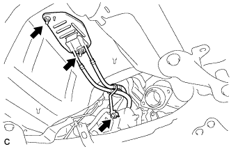
Install the transmission control cable assembly with the 2 nuts and bolt.
- Момент затяжки:
- 5.0 Н*м{51 кгс*см, 44 фунт-сила-дюймов}
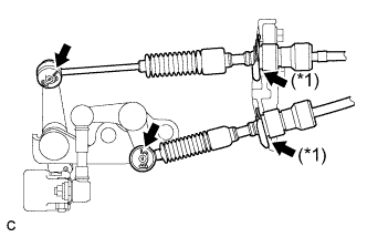
Install the 2 transmission control cables to the control cable bracket with 2 new clips. (*1)
Install the 2 transmission control cables to the manual transaxle with the 2 clips.
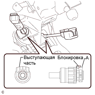
Connect the transmission control cable assembly to the shift lever assembly.
- ПРИМЕЧАНИЕ:
- The projecting part of the cable outer should face upward when the shift cable is connected.
- After installation, make sure that the cable outer lock is projecting from A as shown in the illustration.
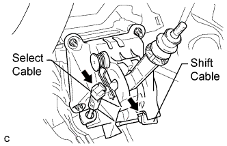
Install the control select cable to the shift lever assembly.
Install the control shift cable to the shift lever assembly.
| 2. ADJUST TRANSMISSION CONTROL SELECT CABLE |
Install the transmission control cable assembly to the manual transaxle.
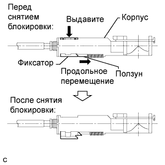
Release the lock of the cable length adjustment structure of the select cable.
Slide the slider.
Push the lock piece downward to release the lock.
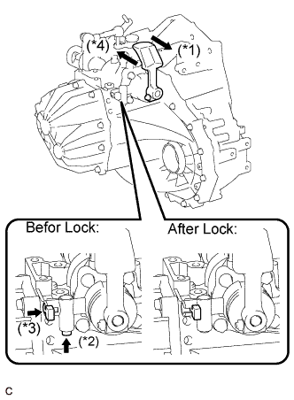
Lock the shift system fixing pin for reverse inhibitor.
Move the shaft in the arrow (*1) direction until it is locked (shaft stroke 15 mm (0.59 in.)).
Press the pin in the arrow (*3) direction until it is locked while pushing the button in the arrow (*2) direction.
While pressing the pin, move the shaft in the arrow (*4) direction until it is locked (shaft stroke 7.3 mm (0.29 in.)).
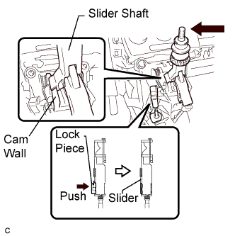
Push the slider shaft until it contacts the cam wall.
- ПРИМЕЧАНИЕ:
- Do not pull up the slider shaft.
- When adjusting the cable, make sure that the shift lever is not in the first or second gear position.
Lock the cable length adjustment structure of the select cable.
- ПРИМЕЧАНИЕ:
- Push the lock piece as far as it will go.
- Confirm whether the cable length adjustment structure is locked securely.
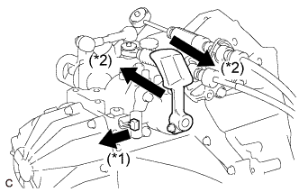
Release the shift system fixing pin for reverse inhibitor.
Move the pin in the arrow (*1) direction until it is locked (pin stroke 8.5 mm (0.33 in.)).
Check that the pin is released by moving the shaft in the arrow (*2) direction.
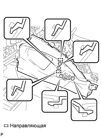
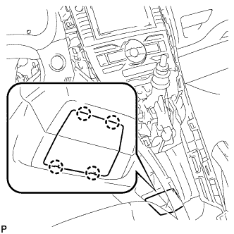
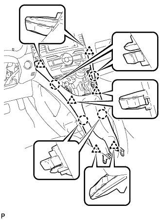
| 3. INSTALL LOWER NO. 1 INSTRUMENT PANEL FINISH PANEL |
Введите в зацепление 2 захвата и направляющую.
Введите в зацепление 4 захвата и 2 направляющие.
Установите нижнюю отделочную накладку панели приборов № 1 и закрепите ее 2 винтами <E> или <F>.
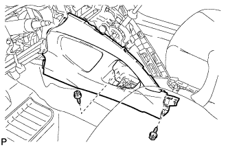
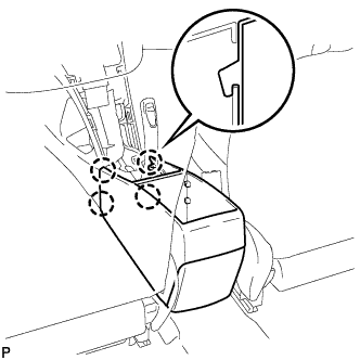
| 4. INSTALL LOWER NO. 2 INSTRUMENT PANEL FINISH PANEL |
Введите в зацепление 2 захвата и направляющую.
Установите нижнюю отделочную накладку панели приборов № 2 и закрепите ее 2 винтами <E> или <F>.
| 5. INSTALL INSTRUMENT PANEL UNDER TRAY |
Установите нижний лоток панели приборов и закрепите его 4 захватами.
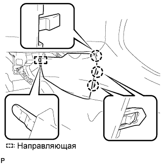
| 6. INSTALL FRONT NO. 1 CONSOLE BOX INSERT |
Введите в зацепление направляющую.
Введите в зацепление 3 захвата и установите переднюю вставку вещевого ящика в облицовке туннеля пола № 1.
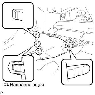
| 7. INSTALL FRONT NO. 2 CONSOLE BOX INSERT |
Введите в зацепление направляющую.
Введите в зацепление 3 захвата и установите переднюю вставку вещевого ящика в облицовке туннеля пола № 2.
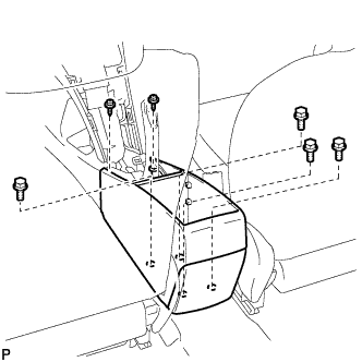
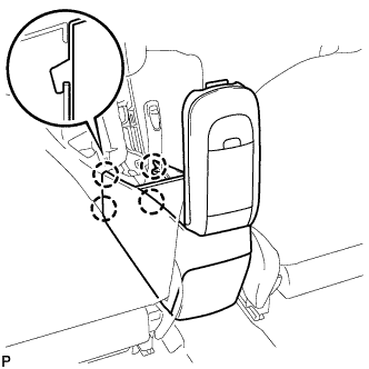
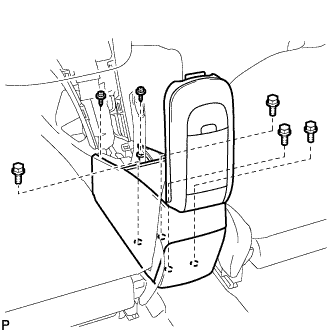
| 8. INSTALL REAR CONSOLE BOX ASSEMBLY (w/o Console Box Lid) |
Введите в зацепление 4 захвата.
Установите вещевой ящик в облицовке туннеля пола и закрепите его 4 болтами и 2 винтами.
| 9. INSTALL REAR CONSOLE BOX ASSEMBLY (w/ Console Box Lid) |
Введите в зацепление 4 захвата.
Установите вещевой ящик в облицовке туннеля пола и закрепите его 4 болтами и 2 винтами.
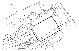
| 10. INSTALL CONSOLE BOX CARPET (w/o Console Box Lid) |
Установите коврик вещевого ящика в облицовке туннеля пола.
| 11. INSTALL CONSOLE BOX CARPET (w/ Console Box Lid) |
Установите коврик вещевого ящика в облицовке туннеля пола.
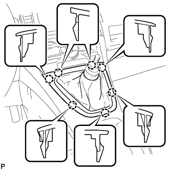
| 12. INSTALL LOWER CENTER INSTRUMENT PANEL FINISH PANEL |
Введите в зацепление 4 захвата и 6 фиксаторов и установите центральную нижнюю облицовочную накладку панели приборов.
| 13. INSTALL UPPER CONSOLE PANEL |
Введите в зацепление 7 захватов и установите верхнюю облицовку панели пола.
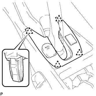
| 14. INSTALL REAR CONSOLE BOX COVER |
Подсоедините разъем.
Установите крышку вещевого ящика в облицовке туннеля пола и закрепите ее 4 фиксаторами.
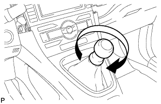
| 15. INSTALL SHIFT LEVER KNOB SUB-ASSEMBLY |
Поверните рукоятку рычага переключения передач по часовой стрелке и закрепите ее.
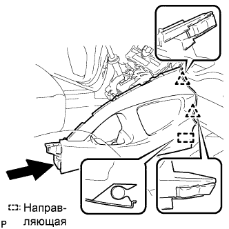
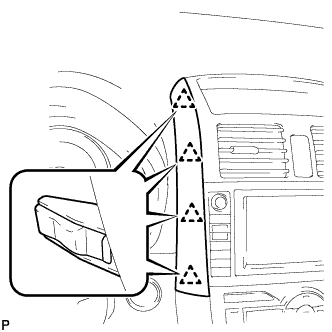
| 16. INSTALL INSTRUMENT PANEL FINISH PANEL END LH |
Введите в зацепление 4 фиксатора и установите левую отделочную накладку панели приборов.
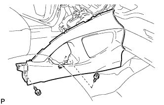
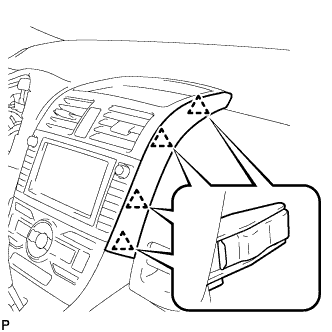
| 17. INSTALL INSTRUMENT PANEL FINISH PANEL END RH |
Введите в зацепление 4 фиксатора и установите правую отделочную накладку панели приборов.
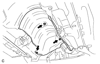
| 18. INSTALL NO. 1 FRONT FLOOR HEAT INSULATOR |
Install the No. 1 front floor heat insulator with the 3 nuts.
- Момент затяжки:
- 5.5 Н*м{56 кгс*см, 49 фунт-сила-дюймов}
| 19. INSTALL FRONT EXHAUST PIPE ASSEMBLY (for 2ZR-FE) |
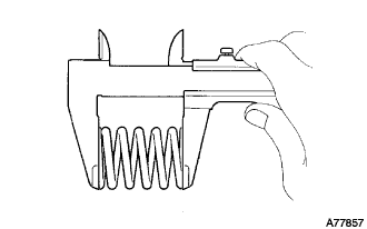
Using vernier calipers, measure the free length of the compression springs.
Minimum (front)
| 41.5 mm (1.63 in.)
|
Minimum (rear)
| 38.5 mm (1.52 in.)
|
- УКАЗАНИЕ:
- If the free length is less than the minimum, replace the compression spring.
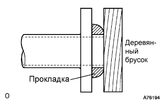
Using a plastic hammer and wooden block, tap in a new gasket until its surface is flush with the exhaust manifold.
- ПРИМЕЧАНИЕ:
- Be careful with the installation direction of the gasket.
- Do not reuse the gasket.
- Do not damage the gasket.
- Do not push in the gasket by using the exhaust pipe when connecting it.
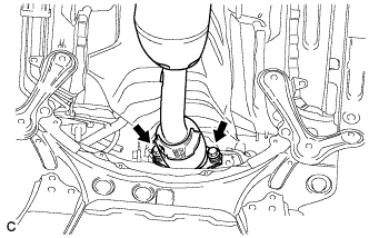
Install the exhaust pipe support, and then install the front exhaust pipe assembly with the 2 compression springs and 2 bolts.
- Момент затяжки:
- 43 Н*м{439 кгс*см, 32 фунт-сила-футов}
Using a plastic hammer and wooden block, tap in a new gasket until its surface is flush with the front exhaust pipe assembly.
- ПРИМЕЧАНИЕ:
- Be careful with the installation direction of the gasket.
- Do not reuse the gasket.
- Do not damage the gasket.
- Do not push in the gasket by using the exhaust pipe when connecting it.
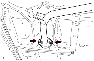
Connect the front exhaust pipe assembly to the center exhaust pipe assembly with the 2 compression springs and 2 bolts.
- Момент затяжки:
- 43 Н*м{439 кгс*см, 32 фунт-сила-футов}
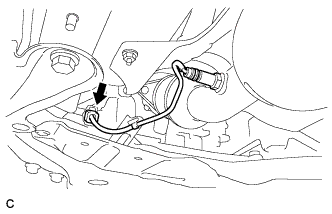
| 20. CONNECT HEATED OXYGEN SENSOR |
Connect the oxygen sensor connector.
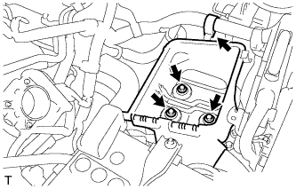
| 21. INSTALL AIR CLEANER CASE SUB-ASSEMBLY (for 2ZR-FE) |
Install the air cleaner case with the 3 bolts.
- Момент затяжки:
- 7.0 Н*м{71 кгс*см, 62 фунт-сила-дюймов}
Install the wire harness clamp to the air cleaner case.
Install the air cleaner filter element.
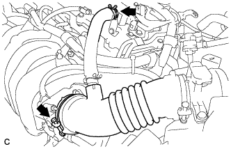
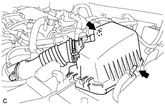
| 22. INSTALL AIR CLEANER CAP SUB-ASSEMBLY (for 2ZR-FE) |
Connect the air cleaner cap sub-assembly with the band.
Connect the ventilation hose.
Connect the 2 clamps.
Connect the mass air flow meter connector.
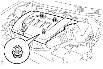
| 23. INSTALL NO. 2 CYLINDER HEAD COVER (for 2ZR-FE) |
Engage the 4 clips to install the V-bank cover.
- ПРИМЕЧАНИЕ:
- Be sure to engage the clips securely.
- Do not apply excessive force or do not hit the cover to engage the clips. This may cause the cover to break.
| 25. INSTALL BATTERY (for 2ZR-FE) |
Install the battery clamp.
- Момент затяжки:
- for bolt:
- 17 Н*м{168 кгс*см, 12 фунт-сила-футов}
- for nut:
- 3.5 Н*м{36 кгс*см, 31 фунт-сила-дюймов}
Install the battery terminal.
- Момент затяжки:
- 5.4 Н*м{55 кгс*см, 48 фунт-сила-дюймов}
| 26. INSTALL RADIATOR UPPER AIR DEFLECTOR |
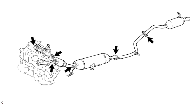
| 27. INSPECT FOR EXHAUST GAS LEAK (for 2ZR-FE) |
Check that there are no exhaust gas leaks from the points (joints of the exhaust pipes and installation points of each sensor) shown in the illustration.