Топливная Система Common Rail -- Установка |
| 1. INSTALL COMMON RAIL ASSEMBLY |
 |
Install the common rail assembly.
Connect the fuel hose.
Install the common rail with the 2 bolts.
- Момент затяжки:
- 26 Н*м{265 кгс*см, 19 фунт-сила-футов}
| 2. INSTALL FUEL INLET PIPE SUB-ASSEMBLY |
 |
- ПРИМЕЧАНИЕ:
- When replacing the common rail, the fuel inlet pipe must also be replaced.
- Replace the fuel inlet pipe with a new one when the fuel inlet pipe has been removed and reinstalled more than 5 times.
Temporarily install the fuel inlet pipe onto the supply pump and common rail.
- ПРИМЕЧАНИЕ:
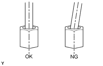
- Install the pipe and union nut vertically, not at a tilt.
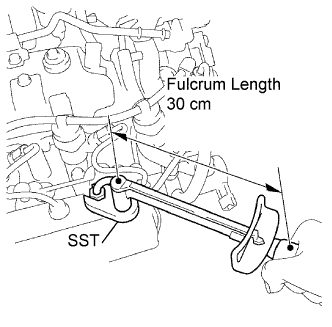
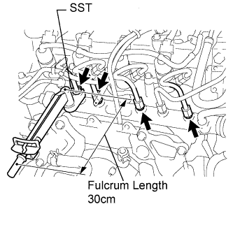
Using SST, tighten the fuel inlet pipe union nut of the fuel inlet pipe on the common rail side.
- SST
- 09023-38401
- Момент затяжки:
- With SST:
- 23 Н*м{235 кгс*см, 17 фунт-сила-футов}
- Without SST:
- 25 Н*м{255 кгс*см, 18 фунт-сила-футов}
- УКАЗАНИЕ:
- Use a torque wrench with a fulcrum length of 30 cm (11.81 in.).
- After the fuel inlet pipe has been reassembled, check that the used pipe has no deflection and is installed properly.
If it has deflection or could not be installed properly, replace the used pipe with a new one.
 |
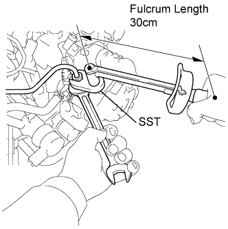
Using a wrench (17 mm), hold the supply pump steadily, and using SST, tighten the fuel inlet pipe union nut of the fuel inlet pipe on the supply pump side.
- SST
- 09023-38401
- Момент затяжки:
- With SST:
- 23 Н*м{235 кгс*см, 17 фунт-сила-футов}
- Without SST:
- 25 Н*м{255 кгс*см, 18 фунт-сила-футов}
- УКАЗАНИЕ:
- Use a torque wrench with a fulcrum length of 30 cm (11.81 in.).
- After the fuel inlet pipe has been reassembled, check that the used pipe has no deflection and is installed properly.
If it has deflection or could not be installed properly, replace the used pipe with a new one.
 |
| 3. INSTALL NO. 1 INJECTION PIPE SUB-ASSEMBLY |
|
- ПРЕДОСТЕРЕЖЕНИЕ:
- When replacing the common rail, the injection pipes must also be replaced.
- Replace the injection pipe with a new one when the injection pipe has been removed and reinstalled more than 5 times.
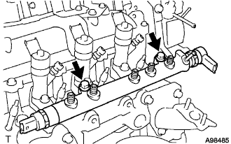
Temporarily install the 4 injection pipes onto the injector and common rail.
- ПРИМЕЧАНИЕ:
- Install the pipe and union nut vertically, not at a tilt.
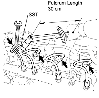
Using SST, tighten the injection pipe union nut of the injection pipe on the common rail side.
- SST
- 09023-38401
- Момент затяжки:
- With SST:
- 23 Н*м{235 кгс*см, 17 фунт-сила-футов}
- Without SST:
- 25 Н*м{255 кгс*см, 18 фунт-сила-футов}
- УКАЗАНИЕ:
- Use a torque wrench with a fulcrum length of 30 cm (11.81 in.).
- After the fuel inlet pipe has been reassembled, check that the used pipe has no deflection and is installed properly.
If it has deflection or could not be installed properly, replace the used pipe with a new one.
 |
Using a wrench (13 mm), hold the injector steadily, and using SST, tighten the injection pipe union nut of the injection pipe with a new one.
- SST
- 09023-38401
- Момент затяжки:
- With SST:
- 23 Н*м{235 кгс*см, 17 фунт-сила-футов}
- Without SST:
- 25 Н*м{255 кгс*см, 18 фунт-сила-футов}
- УКАЗАНИЕ:
- Use a torque wrench with a fulcrum length of 30 cm (11.81 in.).
- After the fuel inlet pipe has been reassembled, check that the used pipe has no deflection and is installed properly.
If it has deflection or could not be installed properly, replace the used pipe with a new one.
 |
| 4. INSTALL NO. 2 INJECTION PIPE SUB-ASSEMBLY |
- SST
- 09023-38401
- УКАЗАНИЕ:
- Perform the same procedure as for the No. 1 injection pipe.
| 5. INSTALL NO. 3 INJECTION PIPE SUB-ASSEMBLY |
- SST
- 09023-38401
| 6. INSTALL NO. 4 INJECTION PIPE SUB-ASSEMBLY |
- SST
- 09023-38401
| 7. INSTALL NO. 2 INJECTION PIPE CLAMP |
| 8. INSTALL NO. 1 INJECTION PIPE CLAMP |
| 9. INSTALL VACUUM REGULATING VALVE ASSEMBLY |
Install the vacuum regulating valve with the 2 bolts.
- Момент затяжки:
- 3.4 Н*м{35 кгс*см, 30 фунт-сила-дюймов}
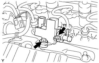 |
Connect the 2 vacuum hoses to the vacuum regulating valve.
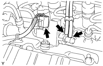 |
Connect the vacuum regulating valve connector.
| 10. INSTALL EGR COOLER ASSEMBLY |
Install 2 new gaskets.
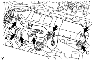 |
Temporarily install the EGR cooler assembly with the bolt and 4 nuts, in the order described below.
Tighten bolt B.
- Момент затяжки:
- 11 Н*м{112 кгс*см, 8 фунт-сила-футов}
Tighten 2 nuts A.
- Момент затяжки:
- 11 Н*м{112 кгс*см, 8 фунт-сила-футов}
Tighten 2 nuts C.
- Момент затяжки:
- 20 Н*м{204 кгс*см, 15 фунт-сила-футов}
Connect the 2 water by-pass hoses.
| 11. INSTALL AIR CLEANER CAP SUB-ASSEMBLY |
Install the air cleaner cap sub-assembly, and connect the 2 clamps and band.
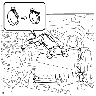 |
Connect the No. 2 ventilation hose.
Connect the mass air flow meter connector.
| 12. INSTALL OIL LEVEL DIPSTICK GUIDE |
Install the oil level gauge guide with the bolt.
- Момент затяжки:
- 11 Н*м{112 кгс*см, 8 фунт-сила-футов}
| 13. CONNECT CABLE TO NEGATIVE BATTERY TERMINAL |
- Момент затяжки:
- 5.4 Н*м{55 кгс*см, 48 фунт-сила-дюймов}
| 14. ADD ENGINE COOLANT |
Tighten the radiator drain cock plug.
Add TOYOTA Super Long Life Coolant (SLLC) to the radiator reservoir filler opening.
- Standard capacity:
Item Specified Condition without Power heater 5.4 liters (5.7 US qts, 4.8 lmp. qts) with Power heater 5.8 liters (6.1 US qts, 5.1 lmp. qts)
- УКАЗАНИЕ:
- TOYOTA vehicles are filled with TOYOTA SLLC at the factory. In order to avoid damage to the engine cooling system and other technical problems, only use TOYOTA SLLC or similar high quality ethylene glycol based non-silicate, non-amine, non-nitrite, non-borate coolant with long-life hybrid organic acid technology (coolant with long-life hybrid organic acid technology consists of a combination of low phosphates and organic acids).
- Contact your TOYOTA dealer for further details.
- ПРИМЕЧАНИЕ:
- Never use water as a substitute for engine coolant.
Remove the radiator cap and air-bleeding valve and add coolant to line B of the reservoir tank.
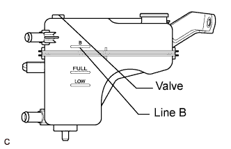 |
Press the inlet and outlet radiator hoses several times by hand, and then check the level of the coolant.
If the coolant level is low, add coolant.
Install the cap and valve, and warm up the engine sufficiently.
Bleed air from the cooling system.
- ПРИМЕЧАНИЕ:
- Before starting the engine, turn the A/C switch OFF.
- Adjust the air conditioner set temperature to MAX (HOT).
- Adjust the air conditioner set blower to Lo.
Warm up the engine until the thermostat opens. While the thermostat is open, allow the coolant to circulate for several minutes.
- УКАЗАНИЕ:
- The thermostat opening timing can be confirmed by squeezing the inlet radiator hose by hand, and sensing vibrations when the engine coolant starts to flow inside the hose.
- ПРЕДОСТЕРЕЖЕНИЕ:
- When squeezing the radiator hose:
- Wear protective gloves.
- Be careful as the radiator hoses are hot.
- Keep your hands away from the radiator fan.
After the engine has warmed up, run the engine using the following cycle for at least 7 minutes: at 3000 rpm for 5 seconds, at idle speed for 45 seconds. (Repeat this cycle at least 8 times.)
Squeeze the inlet and outlet radiator hoses several times by hand to bleed air from the system.
- ПРЕДОСТЕРЕЖЕНИЕ:
- When squeezing the radiator hose:
- Wear protective gloves.
- Be careful as the radiator hoses are hot.
- Keep your hands away from the radiator fan.
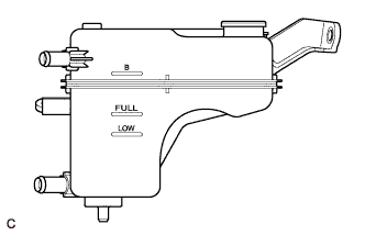
After the engine has cooled down, check that the coolant level is between FULL and LOW.
If the coolant level is low, add coolant to the reservoir tank F line.
 |
| 15. INSPECT FOR COOLANT LEAK |
Remove the radiator reservoir cap.
- ПРЕДОСТЕРЕЖЕНИЕ:
- To avoid the danger of being burned, do not remove the radiator reservoir cap while the engine and radiator are still hot. Thermal expansion will cause hot engine coolant and steam to blow out from the radiator.
Fill the radiator with coolant, and then attach a radiator cap tester.
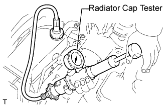 |
Warm up the engine.
Pump the radiator cap tester to 108 kPa (1.1 kgf/cm2, 15.6 psi), and then check that the pressure does not drop.
If the pressure drops, check the hoses, radiator and water pump for leakage.
If there are no signs of external coolant leaks, check the heater core, cylinder block and head.
Reinstall the radiator reservoir cap.
| 16. INSPECT FOR FUEL LEAK |
- УКАЗАНИЕ:
- Using the intelligent tester to perform Active Tests allow relays, VSVs, actuators and other items to be operated without removing any parts. This non-intrusive functional inspection can be very useful because intermittent operation may be discovered before parts or wiring is disturbed. Performing Active Tests early in troubleshooting is one way to save diagnostic time. Data List information can be displayed while performing Active Tests.
- The Data List can be displayed during Active Tests.
Connect an intelligent tester to the DLC3.
Turn the ignition switch to the ON position.
Turn the tester on.
Enter the following menu items: Powertrain / Engine and ECT / Active Test.
Perform the Active Test.
Tester Display Test Part Control Range Diagnostic Notes Active the fuel leak test Pressurize common rail internal fuel pressure, in order to see if fuel leaks ON/OFF - Fuel pressure inside common rail pressurized to 135 MPa and engine speed increased to 2000 rpm when ON selected
- Above conditions preserved while test ON
- Fuel pressure inside common rail pressurized to 135 MPa and engine speed increased to 2000 rpm when ON selected
| 17. INSTALL NO. 1 ENGINE COVER |
Fit the 4 retainers and install the No. 1 engine cover.