Блок Двигателя -- Повторная Сборка |
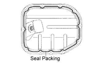
| 1. INSTALL OIL PAN SUB-ASSEMBLY |
Apply a continuous bead of seal packing (Diameter 2.0 to 3.0 mm (0.079 to 0.118 in.)) to the oil pan as illustrated.
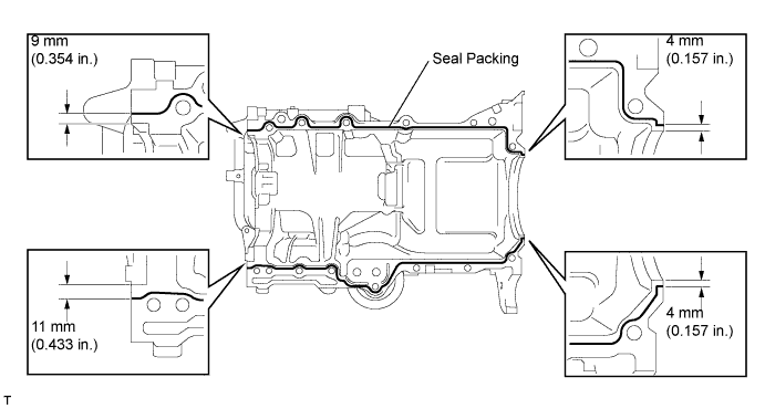
- Seal packing:
- Toyota Genuine Seal Packing Black, Three Bond 1207B or equivalent
- ПРИМЕЧАНИЕ:
- Remove any oil from the contact surface.
- Install the oil pan within 3 minutes, and tighten the bolts within 15 minutes of applying the seal packing.
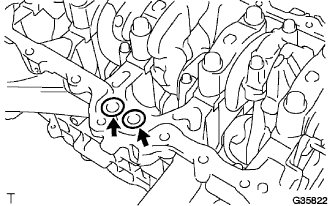
Install 2 new O-rings onto the cylinder block, then install the oil pan.
- ПРИМЕЧАНИЕ:
- Clean the contact surface of the new O-rings.
- Make sure that the O-rings are not twisted when installing the oil pan.
 |
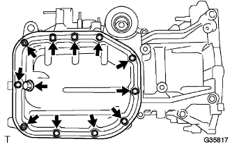
Using several steps, temporarily tighten the 13 bolts in the sequence shown in the illustration, then tighten the bolts to the specified torque.
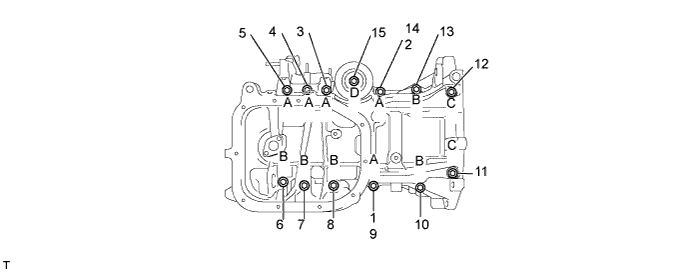
- Момент затяжки:
- 24 Н*м{245 кгс*см, 18 фунт-сила-футов}
- УКАЗАНИЕ:
- The bolt lengths are as follows.
- Bolt A 49 mm (1.93 in.)
- Bolt B 88 mm (3.46 in.)
- Bolt C 143.3 mm (5.64 in.)
- Bolt D 35 mm (1.38 in.)
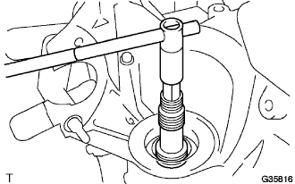
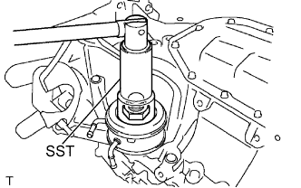
| 2. INSTALL ENGINE REAR OIL SEAL |
Apply MP grease to a new oil seal lip.
- ПРИМЕЧАНИЕ:
- Keep the lip free of foreign matter.
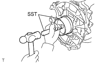 |
Using SST and a hammer, tap in the new oil seal until its surface is flush the cylinder block edge.
- SST
- 09223-15030
09950-70010(09951-07100)
- ПРИМЕЧАНИЕ:
- Tap the oil seal from the vertical position.
- Wipe any extra grease off the crankshaft.
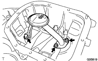
| 3. INSTALL OIL STRAINER SUB-ASSEMBLY |
Install a new gasket, then install the oil strainer with the bolt and 2 nuts.
- Момент затяжки:
- 11 Н*м{112 кгс*см, 8 фунт-сила-футов}
 |
| 4. INSTALL NO. 2 OIL PAN SUB-ASSEMBLY |
Apply a continuous bead of seal packing (Diameter 2.5 to 3.5 mm (0.0984 to 0.1378 in.)) to the oil pan as illustrated.
- Seal packing:
- Toyota Genuine Seal Packing Black, Three Bond 1207B or equivalent
- ПРИМЕЧАНИЕ:
- Remove any oil from the contact surface.
- Install the oil pan within 3 minutes, and tighten the bolts within 15 minutes of applying the seal packing.
 |
Install No. 2 oil pan with the 9 bolts and 2 nuts.
- Момент затяжки:
- 9.0 Н*м{92 кгс*см, 80 фунт-сила-дюймов}
 |
Install a new gasket and oil pan drain plug.
- Момент затяжки:
- 38 Н*м{387 кгс*см, 28 фунт-сила-футов}
| 5. INSTALL OIL FILTER UNION |
Using a 12 mm socket hexagon wrench, install the oil filter union.
- Момент затяжки:
- 30 Н*м{306 кгс*см, 22 фунт-сила-футов}
 |
| 6. INSTALL OIL COOLER ASSEMBLY |
Clean the oil cooler installation surface of the engine.
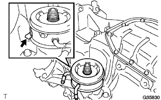 |
Apply a light coat of engine oil to the O-ring of the oil cooler.
Place the stopper portion on the oil pan side, and fix the oil cooler with the nut.
Using SST, tighten the nut to the specified torque.
- SST
- 09229-55010
- Момент затяжки:
- 66 Н*м{673 кгс*см, 49 фунт-сила-футов}
 |
| 7. INSTALL OIL FILTER SUB-ASSEMBLY |
Check and clean the oil filter installation surface.
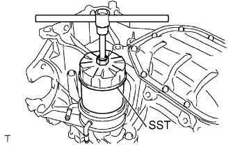 |
Apply clean engine oil to the gasket of a new oil filter.
Lightly screw the oil filter into place, then tighten it until the gasket comes into contact with the seat.
Using SST, tighten it an additional 3/4 turn.
- SST
- 09228-07501
- Момент затяжки:
- 13 Н*м{133 кгс*см, 10 фунт-сила-футов}
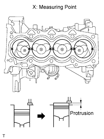
| 8. INSTALL CYLINDER HEAD GASKET |
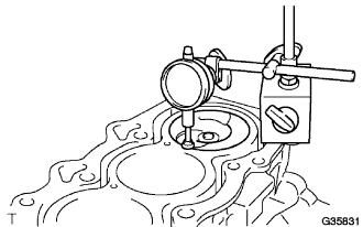
Inspect the protrusion height of the piston heads.
Place a dial indicator on the cylinder block as shown in the illustration.
- ПРИМЕЧАНИЕ:
- Make sure that the dial indicator is at right angles to cylinder block upper surface.
Measure the protrusion height of the piston head for each cylinder in 2 places as shown in the illustration.
 |
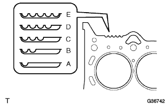
Select a new cylinder head gasket.
Select the highest protrusion height among the 8 measurements records. It is used to select a new cylinder head gasket.
Piston protrusion: Piston protrusion
mm (in.)Gasket cutout Gasket size 0.375 to 0.425
(0.015 to 0.017)1 A 0.425 to 0.475
(0.017 to 0.019)2 B 0.475 to 0.525
(0.019 to 0.021)3 C 0.525 to 0.575
(0.021 to 0.023)4 D 0.575 to 0.625
(0.023 to 0.025)5 E
 |
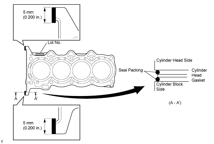
Install the cylinder head gasket.
Apply seal packing (Diameter 3.5 to 4.5 mm (0.138 to 0.177 in.)) to the cylinder block side as shown in the illustration.
- Seal packing:
- Toyota Genuine Seal Packing Black, Three Bond 1207B or equivalent
- ПРИМЕЧАНИЕ:
- Remove any oil from the contact surface.
Place a new cylinder head gasket on the cylinder block with the Lot No. stamp facing upward.
Apply seal packing (Diameter 3.5 to 4.5 mm (0.138 to 0.177 in.)) to the top surface of the cylinder head again as shown in the illustration.
- Seal packing:
- Toyota Genuine Seal Packing Black, Three Bond 1207B or equivalent
Install the cylinder head onto the cylinder block.
- ПРИМЕЧАНИЕ:
- Remove any oil from the contact surface.
- Install the cylinder head within 3 minutes, and tighten the bolts within 15 minutes of applying the seal packing.
| 9. INSTALL CYLINDER HEAD SUB-ASSEMBLY |
- УКАЗАНИЕ:
- The cylinder head bolts are tightened in 2 successive steps.
Apply a light coat of engine oil to the threads of the cylinder head bolts.
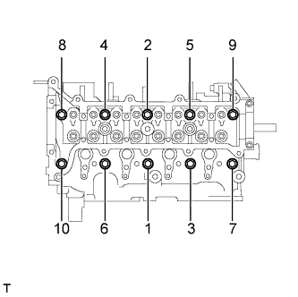 |
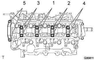
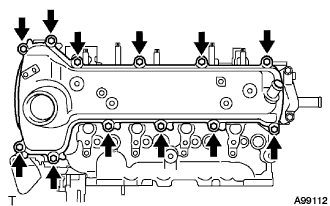
Using several passes, uniformly install and tighten the 10 cylinder head bolts and plate washers in the sequence shown in the illustration. (*1)
- Момент затяжки:
- 68 Н*м{693 кгс*см, 50 фунт-сила-футов}
Mark the front of the cylinder head bolts with paint.
 |
Using the same sequence as step (*1), retighten the cylinder head bolts by additional 90° and one more additional 90° as shown in the illustration.
Check that each paint mark is now 180° opposite from the front.
| 10. INSTALL NO. 1 VALVE ROCKER ARM SUB-ASSEMBLY |
Apply engine oil to the stem end caps, valve rocker arm pivot top surfaces and valve rocker arm roller portions.
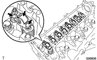 |
Install the 8 valve rocker arms.
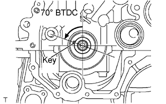
| 11. INSTALL CAMSHAFT |
Turn the crankshaft to set the key in the 70° BTDC position.
 |
Apply engine oil to the camshaft journal portion and cam portion.
Examine the front marks and numbers and check that the sequence is as shown in the illustration. Then, temporarily tighten the camshaft with the camshaft bearing caps and bolts.
- ПРИМЕЧАНИЕ:
- Do not tilt the valve rocker arm when installing the camshaft onto the cylinder head.
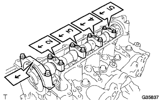 |
Using several steps, temporarily tighten the bolts in the sequence shown in the illustration, and then tighten the bolts to the specified torque.
- Момент затяжки:
- 19 Н*м{194 кгс*см, 14 фунт-сила-футов}
 |
| 12. INSTALL CHAIN SUB-ASSEMBLY |
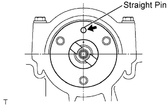
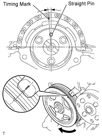
Turn the camshaft to set the straight pin in the position shown in the illustration.
 |
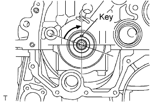
Turn the crankshaft to set the key in the position shown in the illustration.
 |
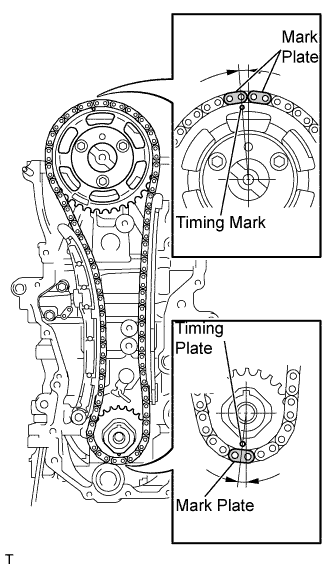
Align the yellow mark plate on the chain with the timing marks on the crankshaft timing sprocket and camshaft timing sprocket.
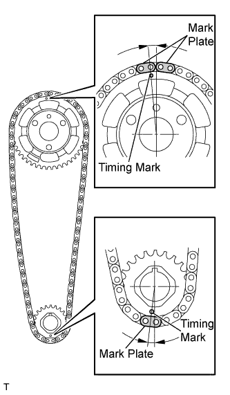 |
Install the chain, camshaft timing sprocket and crankshaft sprocket together onto the engine.
 |
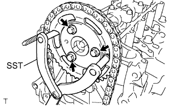
Using SST, fix the camshaft timing sprocket, and install the camshaft timing sprocket with 3 new bolts.
- SST
- 09960-10010(09962-01000,09963-01000)
- Момент затяжки:
- 20 Н*м{204 кгс*см, 15 фунт-сила-футов}
 |
| 13. INSTALL NO. 1 CHAIN VIBRATION DAMPER |
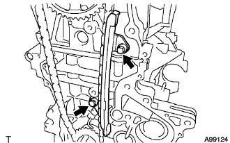
Install the chain vibration damper with the 2 bolts.
- Момент затяжки:
- 20 Н*м{204 кгс*см, 15 фунт-сила-футов}
 |
| 14. INSTALL CHAIN TENSIONER SLIPPER |
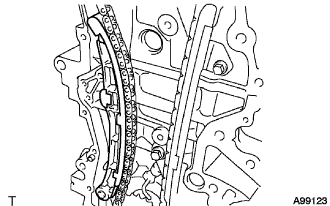
Install the chain tensioner slipper onto the cylinder block.
 |
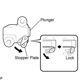
| 15. INSTALL NO. 1 CHAIN TENSIONER ASSEMBLY |
Pull up the stopper plate to unlock the plunger.
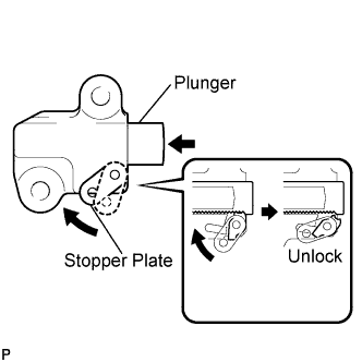 |
Push the plunger to the end with the plunger unlocked.
Pull down the stopper plate, with the plunger pushed to the end, to lock the plunger.
 |
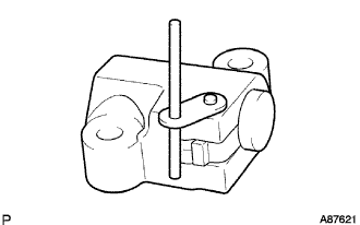
Insert a 2.5 mm (0.098 in.) diameter bar into the hole in the stopper plate with the plunger locked.
- УКАЗАНИЕ:
- If the stopper plate is not completely pulled down and a 2.5 mm (0.098 in.) diameter bar cannot be inserted, unlock and pull out the plunger slightly. The stopper plate will be completely pulled down and a 2.5 mm (0.098 in.) diameter bar can be inserted easily.
 |
Install the chain tensioner with the 2 bolts.
- Момент затяжки:
- 9.0 Н*м{92 кгс*см, 80 фунт-сила-дюймов}
 |
Remove the 2.5 mm (0.098 in.) diameter bar from the chain tensioner.
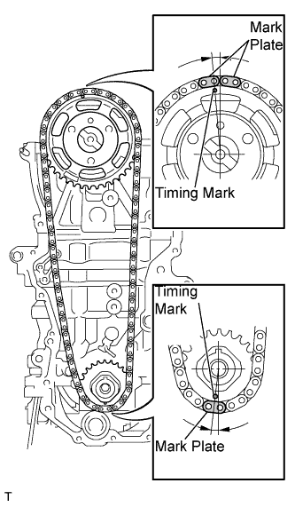
Check that the mark plate and timing mark are in the positions shown in the illustration.
 |
| 16. INSTALL OIL PUMP ASSEMBLY |
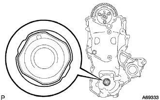
Apply adhesive to 2 or 3 threads of the service hole screw plug bolt end.
- Adhesive:
- Toyota Genuine Adhesive 1324, Three Bond 1324, or equivalent
- ПРИМЕЧАНИЕ:
- Remove any oil from the bolts and bolt holes.
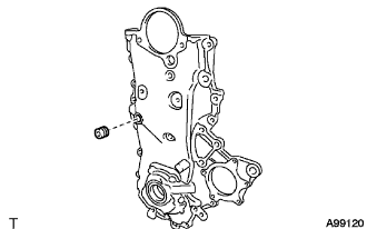 |
Using an 8 mm socket hexagon wrench, install the service hole screw plug.
- Момент затяжки:
- 15 Н*м{153 кгс*см, 11 фунт-сила-футов}
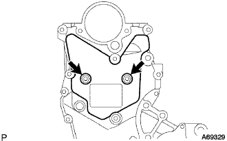
Install 2 new O-rings in the 2 locations shown in the illustration.
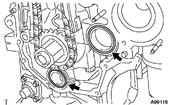 |
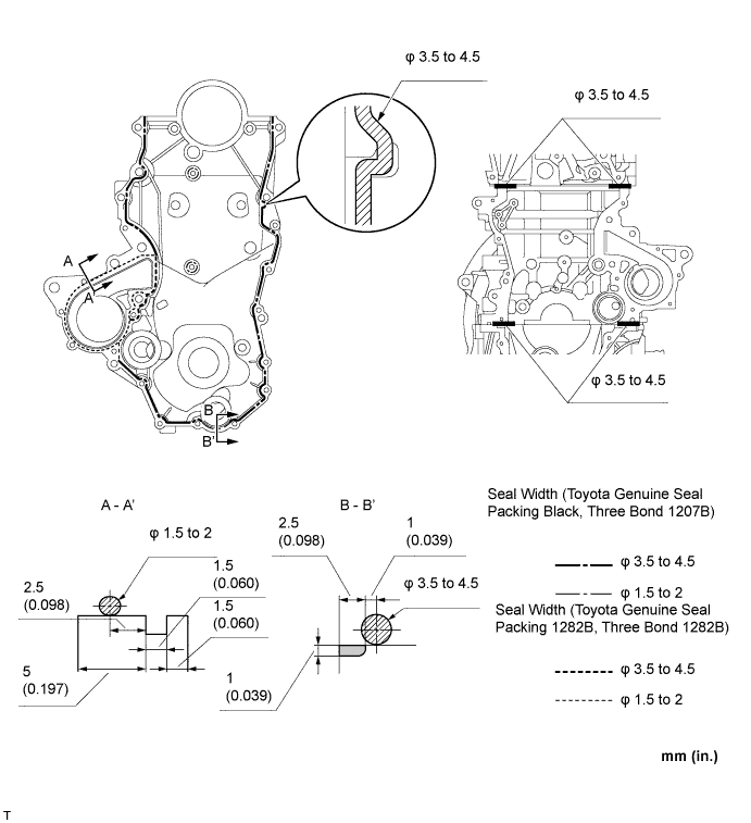
Apply seal packing to the engine body and oil pump as shown in the illustration below.
- ПРИМЕЧАНИЕ:
- Remove any oil from the contact surface.
- Install the oil pan within 3 minutes, and tighten the bolts within 15 minutes of applying the seal packing.
- Seal packing:
- Water pump: Toyota Genuine Seal Packing 1282B, Three Bond 1282B or equivalent
- Other: Toyota Genuine Seal Packing Black, Three Bond 1207B or equivalent
Align the keyway of the oil pump drive rotor with the rectangular portion of the crankshaft, then slide the oil pump into place.
 |
Install the oil pump assembly with the 16 bolts and nut as illustrated.
- Момент затяжки:
- Bolt A:
- 11 Н*м{112 кгс*см, 8 фунт-сила-футов}
- Bolt B:
- 24 Н*м{245 кгс*см, 18 фунт-сила-футов}
- Bolt C:
- 11 Н*м{112 кгс*см, 8 фунт-сила-футов}
- Bolt D:
- 24 Н*м{245 кгс*см, 18 фунт-сила-футов}
- Nut:
- 24 Н*м{245 кгс*см, 18 фунт-сила-футов}
- ПРИМЕЧАНИЕ:
- Make sure that the chain does not come into contact with the seal packing when installing the oil pump.
- Install the engine mounting bracket RH and water pump within 15 minutes of installing the oil pump.
- УКАЗАНИЕ:
- The lengths are as follows.
- Bolt A 20 mm (0.79 in.)
- Bolt B 30 mm (1.18 in.)
- Bolt C 35 mm (1.38 in.)
- Bolt D 20 and 14 mm (0.79 and 0.55 in.) double ended bolt
 |
| 17. INSTALL NO. 2 TIMING CHAIN COVER |
Install the No. 2 timing chain cover with the 2 bolts.
- Момент затяжки:
- 5.5 Н*м{56 кгс*см, 49 фунт-сила-дюймов}
 |
| 18. INSTALL WATER PUMP ASSEMBLY |
Install a new gasket, then install the water pump with the 3 bolts and 2 nuts.
- Момент затяжки:
- 11 Н*м{112 кгс*см, 8 фунт-сила-футов}
 |
| 19. INSTALL CRANKSHAFT DAMPER SUB-ASSEMBLY |
Align the key with the key groove of the crankshaft damper, and slide the crankshaft damper to the crankshaft.
 |
Using SST, secure the crankshaft damper.
- SST
- 09960-10010(09962-01000,09963-01000)
Tighten the bolt to the specified torque.
- Момент затяжки:
- 180 Н*м{1835 кгс*см, 133 фунт-сила-футов}
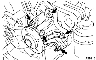
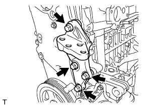
| 20. INSTALL TRANSVERSE ENGINE ENGINE MOUNTING BRACKET |
Install the engine mounting bracket with the 4 bolts.
- Момент затяжки:
- 55 Н*м{561 кгс*см, 41 фунт-сила-футов}
 |
| 21. INSTALL WATER PUMP PULLEY |
Temporarily install the water pump pulley with the 4 bolts.
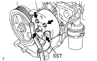 |
Using SST, secure the water pump pulley.
- SST
- 09960-10010(09962-01000,09963-00700)
Tighten the 4 bolts to the specified torque.
- Момент затяжки:
- 15 Н*м{153 кгс*см, 11 фунт-сила-футов}
| 22. INSTALL THERMOSTAT |
Install a new gasket onto the thermostat.
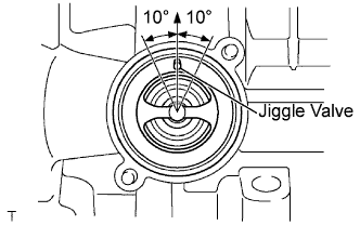 |
Install the thermostat with the jiggle valve facing upward.
- УКАЗАНИЕ:
- The jiggle valve should be set within 10° of the vertical position as illustrated.
Install the water inlet with the 2 nuts.
- Момент затяжки:
- 9.0 Н*м{92 кгс*см, 80 фунт-сила-дюймов}
 |
| 23. INSPECT VALVE CLEARANCE |
Set the No. 1 cylinder to TDC/Compression.
Turn the crankshaft pulley until the grooves of the crankshaft damper and oil pump are aligned.
Check that the timing mark of the camshaft timing sprocket and the straight pin hole in the camshaft timing sprocket are in the positions as shown in the illustration.
- УКАЗАНИЕ:
- If not, turn the crankshaft damper 1 revolution (360°) to align them as above.
 |
Check the valve clearance of the No. 1 cylinder exhaust valve and the No. 2 cylinder intake valve.
Using a feeler gauge, measure the clearance between the camshaft and No. 1 valve rocker arm.
- Valve clearance (Cold):
- 0.11 to 0.17 mm (0.004 to 0.007 in.) for intake
- 0.14 to 0.20 mm (0.006 to 0.008 in.) for exhaust
- ПРИМЕЧАНИЕ:
- Insert the feeler gauge into the center of the roller surface, parallel to No. 1 valve rocker arm.
- Do not apply excessive force to the valve adjusting screw when using adjusting tools such as SST and a screwdriver.
- УКАЗАНИЕ:
- If the clearance is not as specified, record the out-of-specification measurement, then adjust the valve clearance.
 |
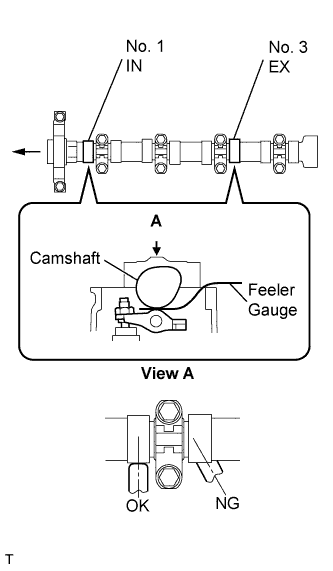
Check the valve clearance of the No. 1 cylinder intake valve and the No. 3 cylinder exhaust valve.
Turn the crankshaft clockwise by a further 180°.
Using a feeler gauge, measure the clearance between the camshaft and No. 1 valve rocker arm as shown in the illustration.
- Valve clearance (Cold):
- 0.11 to 0.17 mm (0.004 to 0.007 in.) for intake
- 0.14 to 0.20 mm (0.006 to 0.008 in.) for exhaust
- ПРИМЕЧАНИЕ:
- Insert the feeler gauge into the center of the roller surface, parallel to No. 1 valve rocker arm.
- Do not apply excessive force to the valve adjusting screw when using adjusting tools such as SST and a screwdriver.
- УКАЗАНИЕ:
- If the clearance is not as specified, record the out-of-specification measurement, then adjust the valve clearance.
 |
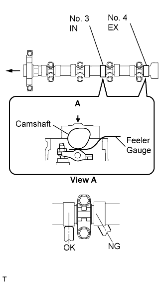
Check the valve clearance of the No. 3 cylinder intake valve and the No. 4 cylinder exhaust valve.
Turn the crankshaft clockwise by a further 180°.
Using a feeler gauge, measure the clearance between the camshaft and No. 1 valve rocker arm as shown in the illustration.
- Valve clearance (Cold):
- 0.11 to 0.17 mm (0.004 to 0.007 in.) for intake
- 0.14 to 0.20 mm (0.006 to 0.008 in.) for exhaust
- ПРИМЕЧАНИЕ:
- Insert the feeler gauge into the center of the roller surface, parallel to No. 1 valve rocker arm.
- Do not apply excessive force to the valve adjusting screw when using adjusting tools such as SST and a screwdriver.
- УКАЗАНИЕ:
- If the clearance is not as specified, record the out-of-specification measurement, then adjust the valve clearance.
 |
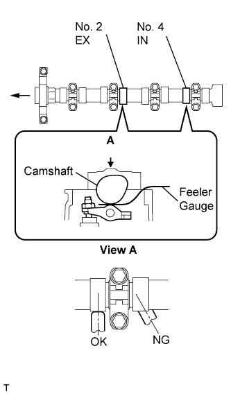
Check the valve clearance of the No. 2 cylinder intake valve and the No. 4 cylinder intake valve.
Turn the crankshaft clockwise by a further 180°.
Using a feeler gauge, measure the clearance between the camshaft and No. 1 valve rocker arm as shown in the illustration.
- Valve clearance (Cold):
- 0.11 to 0.17 mm (0.004 to 0.007 in.) for intake
- 0.14 to 0.20 mm (0.006 to 0.008 in.) for exhaust
- ПРИМЕЧАНИЕ:
- Insert the feeler gauge into the center of the roller surface, parallel to No. 1 valve rocker arm.
- Do not apply excessive force to the valve adjusting screw when using adjusting tools such as SST and a screwdriver.
- УКАЗАНИЕ:
- If the clearance is not as specified, record the out-of-specification measurement, then adjust the valve clearance.
 |
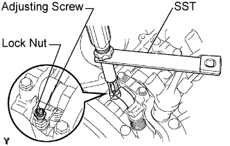
| 24. ADJUST VALVE CLEARANCE |
Using SST and a screwdriver, loosen the valve adjusting nut while keeping the valve adjusting screw in position.
- SST
- 09248-56010
 |
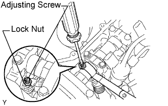
Adjust the valve clearance (intake side).
Insert a thickness gauge (0.14 mm (0.006 in.)) between the camshaft and No. 1 valve rocker arm, and turn the valve adjusting screw to adjust it.
- Valve clearance (Cold):
- 0.14 mm (0.006 in.)
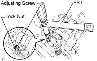
Using SST and a screwdriver, tighten the valve adjusting nut while keeping the adjusting screw in position.
- Момент затяжки:
- with SST:
- 13 Н*м{133 кгс*см, 9.6 фунт-сила-футов}
- with out SST:
- 20 Н*м{204 кгс*см, 15 фунт-сила-футов}
- SST
- 09248-56010
 |
Adjust the valve clearance (exhaust side).
- Valve clearance (Cold):
- 0.17 mm (0.007 in.)
- УКАЗАНИЕ:
- Perform the same procedure as for the intake valve clearance adjustment.
| 25. INSTALL CYLINDER HEAD COVER SUB-ASSEMBLY |
Install the cylinder head gasket onto the cylinder head cover.
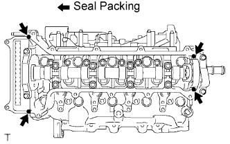 |
Apply seal packing to the 4 locations shown in the illustration, then install the cylinder head cover.
- Seal packing:
- Toyota Genuine Seal Packing Black, Three Bond 1207B or equivalent
- ПРИМЕЧАНИЕ:
- Remove any oil from the contact surface.
- Install the cylinder head cover within 3 minutes, and tighten the bolts within 15 minutes of applying the seal packing.
Temporarily tighten the cylinder head cover with the 12 bolts.
 |
Tighten the bolts to the specified torque as shown in the illustration.
- Момент затяжки:
- 13 Н*м{133 кгс*см, 10 фунт-сила-футов}
| 26. INSTALL OIL FILLER CAP SUB-ASSEMBLY |
Install the oil filler cap gasket onto the oil filler cap.
Install the oil filler cap onto the cylinder head cover.