Прокладка Головки Блока Цилиндров Снятие. Corolla Auris
Двигатель. COROLLA, AURIS. ZZE150 ZRE151,152 NDE150
REMOVE FRONT WHEEL RH
DRAIN ENGINE OIL
DRAIN ENGINE COOLANT
REMOVE NO. 1 ENGINE UNDER COVER
REMOVE ENGINE UNDER COVER REAR RH
REMOVE FRONT SUSPENSION MEMBER REINFORCEMENT RH
REMOVE BATTERY
REMOVE FRONT WIPER ARM HEAD CAP
REMOVE WINDSHIELD WIPER ARM AND BLADE ASSEMBLY LH (for Sedan)
REMOVE WINDSHIELD WIPER ARM AND BLADE ASSEMBLY RH (for Sedan)
REMOVE WINDSHIELD WIPER ARM AND BLADE ASSEMBLY LH (for Hatchback)
REMOVE WINDSHIELD WIPER ARM AND BLADE ASSEMBLY RH (for Hatchback)
REMOVE HOOD TO COWL TOP SEAL
REMOVE COWL TOP VENTILATOR LOUVER RH (for Sedan)
REMOVE COWL TOP VENTILATOR LOUVER LH (for Sedan)
REMOVE COWL TOP VENTILATOR LOUVER RH (for Hatchback)
REMOVE COWL TOP VENTILATOR LOUVER LH (for Hatchback)
REMOVE WINDSHIELD WIPER MOTOR AND LINK (for Sedan)
REMOVE WINDSHIELD WIPER MOTOR AND LINK (for Hatchback)
REMOVE COWL BODY MOUNTING REINFORCEMENT LH (for Hatchback)
REMOVE COWL TOP PANEL OUTER (for Sedan)
REMOVE COWL TOP PANEL OUTER (for Hatchback)
REMOVE NO. 1 ENGINE COVER
REMOVE AIR CLEANER CAP SUB-ASSEMBLY
REMOVE AIR CLEANER FILTER ELEMENT SUB-ASSEMBLY
REMOVE AIR CLEANER CASE SUB-ASSEMBLY
REMOVE BATTERY CARRIER
REMOVE NO. 1 GLOW PLUG CONNECTOR
REMOVE GLOW PLUG ASSEMBLY
REMOVE VACUUM REGULATING VALVE ASSEMBLY
REMOVE EGR COOLER ASSEMBLY
REMOVE EGR VALVE ASSEMBLY
REMOVE DIESEL THROTTLE BODY ASSEMBLY
REMOVE INTAKE AIR CONNECTOR
REMOVE EGR PIPE CONNECTOR
REMOVE NO. 1 INJECTION PIPE CLAMP
REMOVE NO. 2 INJECTION PIPE CLAMP
REMOVE NO. 1 INJECTION PIPE SUB-ASSEMBLY
REMOVE NO. 2 INJECTION PIPE SUB-ASSEMBLY
REMOVE NO. 3 INJECTION PIPE SUB-ASSEMBLY
REMOVE NO. 4 INJECTION PIPE SUB-ASSEMBLY
REMOVE NOZZLE LEAKAGE PIPE ASSEMBLY
REMOVE INJECTOR ASSEMBLY
REMOVE FUEL INLET PIPE SUB-ASSEMBLY
REMOVE COMMON RAIL ASSEMBLY
REMOVE SUPPLY PUMP ASSEMBLY
REMOVE FRONT EXHAUST PIPE ASSEMBLY
REMOVE NO. 1 TURBO INSULATOR
REMOVE EXHAUST MANIFOLD CONVERTER SUB-ASSEMBLY
REMOVE TURBO OIL INLET PIPE
REMOVE NO. 1 AIR HOSE
REMOVE TURBO CHARGER SUB-ASSEMBLY
REMOVE TURBO OIL OUTLET PIPE
REMOVE EXHAUST MANIFOLD
REMOVE V-RIBBED BELT
REMOVE GENERATOR ASSEMBLY
REMOVE ENGINE MOUNTING INSULATOR SUB-ASSEMBLY RH
REMOVE WATER PUMP PULLEY
REMOVE WATER PUMP ASSEMBLY
REMOVE CYLINDER HEAD COVER SUB-ASSEMBLY
REMOVE VACUUM PUMP ASSEMBLY
REMOVE CRANK SHAFT DAMPER SUB-ASSEMBLY
REMOVE NO. 2 TIMING CHAIN COVER
REMOVE OIL PUMP ASSEMBLY
REMOVE OIL PUMP SEAL
REMOVE NO. 1 CHAIN TENSIONER ASSEMBLY
REMOVE CHAIN TENSIONER SLIPPER
REMOVE NO. 1 CHAIN VIBRATION DAMPER
REMOVE CHAIN SUB-ASSEMBLY
REMOVE CAMSHAFT
REMOVE NO. 1 VALVE ROCKER ARM SUB-ASSEMBLY
REMOVE OIL LEVEL GAUGE GUIDE
DISCONNECT MANIFOLD ABSOLUTE PRESSURE SENSOR HOSE
DISCONNECT NO. 1 RADIATOR HOSE
DISCONNECT HEATER INLET WATER HOSE
DISCONNECT HEATER OUTLET WATER HOSE
REMOVE ENGINE COOLANT TEMPERATURE SENSOR
DISCONNECT OIL COOLER HOSE SUB-ASSEMBLY
REMOVE NO. 1 WATER BY-PASS PIPE
REMOVE CYLINDER HEAD SUB-ASSEMBLY
REMOVE CYLINDER HEAD GASKET
Прокладка Головки Блока Цилиндров -- Снятие |
Remove the oil filler cap.
Remove the oil drain plug and drain the oil into a container.
Clean and install the oil drain plug with a new gasket.
- Момент затяжки:
- 38 Н*м{387 кгс*см, 28 фунт-сила-футов}
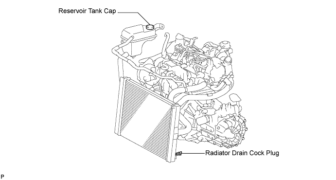
Loosen the radiator drain cock plug.
- УКАЗАНИЕ:
- Collect the coolant in a container and dispose of it according to the regulations in your area.
Remove the radiator reservoir cap.
- ПРЕДОСТЕРЕЖЕНИЕ:
- Do not remove the radiator reservoir cap while the engine and radiator are still hot.
- Pressurized, hot engine coolant and steam may be released and cause serious burns.
Loosen the cylinder block drain cock plug.
- УКАЗАНИЕ:
- The plug is on the backside of the generator on the exhaust manifold side.
| 4. REMOVE NO. 1 ENGINE UNDER COVER |
Disengage the 4 pins and remove No. 1 engine cover sub-assembly.
| 5. REMOVE ENGINE UNDER COVER REAR RH |
Remove the 5 clips and engine under cover rear RH.
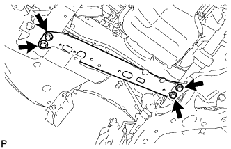
| 6. REMOVE FRONT SUSPENSION MEMBER REINFORCEMENT RH |
Выверните 4 болта и снимите правое усиление элемента передней подвески.
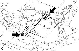
Loosen the bolt and nut, and remove the battery clamp.
Remove the battery and battery tray.
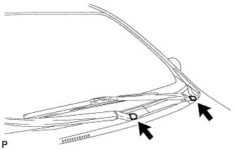
| 8. REMOVE FRONT WIPER ARM HEAD CAP |
Снимите 2 крышки рычага стеклоочистителя ветрового стекла.
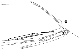
| 9. REMOVE WINDSHIELD WIPER ARM AND BLADE ASSEMBLY LH (for Sedan) |
Отверните гайку и снимите рычаг левого переднего стеклоочистителя со щеткой в сборе.
| 10. REMOVE WINDSHIELD WIPER ARM AND BLADE ASSEMBLY RH (for Sedan) |
Отверните гайку и снимите рычаг правого переднего стеклоочистителя со щеткой в сборе.
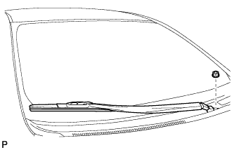
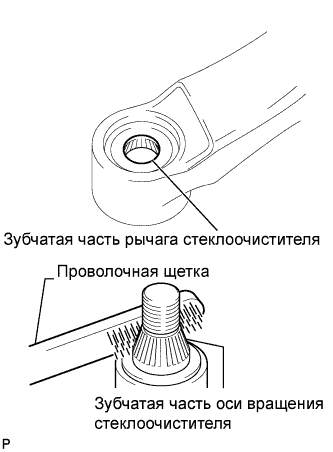
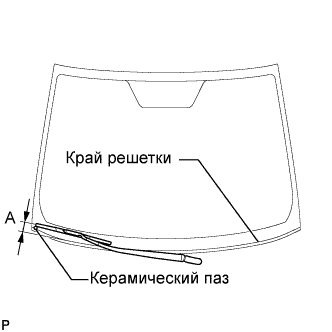
| 11. REMOVE WINDSHIELD WIPER ARM AND BLADE ASSEMBLY LH (for Hatchback) |
Приведите в действие стеклоочиститель и остановите электродвигатель стеклоочистителя ветрового стекла в положении автоматического ограничения хода.
Очистите зубчатую часть рычага стеклоочистителя.
При повторной установке:
Почистите зубчатую часть оси вращения стеклоочистителя проволочной щеткой.
Установите правый рычаг переднего стеклоочистителя со щеткой в сборе, как показано на рисунке, и закрепите их гайкой.
- Момент затяжки:
- 26 Н*м{265 кгс*см, 19 фунт-сила-футов}
- УКАЗАНИЕ:
- Удерживайте шарнир рычага рукой, чтобы затянуть гайку.
Участок
| Измерение
|
А
| 17,5–32,5 мм (0,69–1,28 дюйма)
|
| 12. REMOVE WINDSHIELD WIPER ARM AND BLADE ASSEMBLY RH (for Hatchback) |
Приведите в действие стеклоочиститель и остановите электродвигатель стеклоочистителя ветрового стекла в положении автоматического ограничения хода.
Очистите зубчатую часть рычага стеклоочистителя.
При повторной установке:
Почистите зубчатую часть оси вращения стеклоочистителя проволочной щеткой.
Установите правый рычаг переднего стеклоочистителя со щеткой в сборе, как показано на рисунке, и закрепите их гайкой.
- Момент затяжки:
- 26 Н*м{265 кгс*см, 19 фунт-сила-футов}
- УКАЗАНИЕ:
- Удерживайте шарнир рычага рукой, чтобы затянуть гайку.
Участок
| Измерение
|
А
| 17,5–32,5 мм (0,39–1,57 дюйма)
|
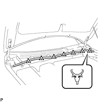
| 13. REMOVE HOOD TO COWL TOP SEAL |
Освободите 7 фиксаторов и снимите верхнее уплотнение между капотом и кожухом.
| 14. REMOVE COWL TOP VENTILATOR LOUVER RH (for Sedan) |
Освободите 14 захватов и зажим и снимите правую вентиляционную решетку в верхней части кожуха.
| 15. REMOVE COWL TOP VENTILATOR LOUVER LH (for Sedan) |
Освободите 8 захватов и зажим и снимите левую вентиляционную решетку в верхней части кожуха.
| 16. REMOVE COWL TOP VENTILATOR LOUVER RH (for Hatchback) |
Освободите 11 захватов и зажим и снимите правую вентиляционную решетку в верхней части кожуха.
| 17. REMOVE COWL TOP VENTILATOR LOUVER LH (for Hatchback) |
Освободите 6 захватов и зажим и снимите левую вентиляционную решетку в верхней части кожуха.
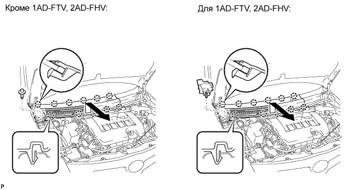
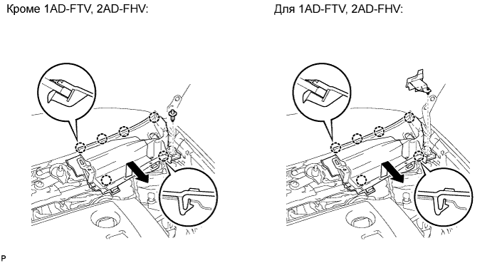
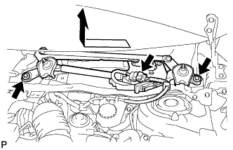
| 18. REMOVE WINDSHIELD WIPER MOTOR AND LINK (for Sedan) |
Отсоедините разъем.
Выверните 2 болта и снимите электродвигатель стеклоочистителя ветрового стекла с тягой в сборе.
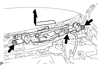
| 19. REMOVE WINDSHIELD WIPER MOTOR AND LINK (for Hatchback) |
Отсоедините разъем.
Выверните 2 болта и снимите электродвигатель стеклоочистителя ветрового стекла с тягой в сборе.
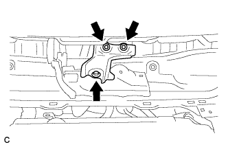
| 20. REMOVE COWL BODY MOUNTING REINFORCEMENT LH (for Hatchback) |
Выверните 3 болта и снимите левый усилитель крепления кожуха к кузову.
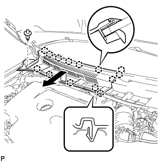
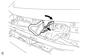
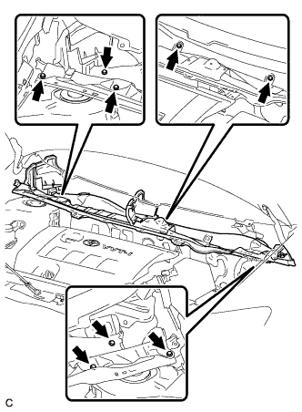
| 21. REMOVE COWL TOP PANEL OUTER (for Sedan) |
Освободите зажим и отогните правую водозащитную пластину, как показано на рисунке.
Расцепите зажим.
Выверните 10 болтов и снимите наружную верхнюю панель кожуха.
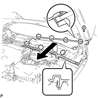
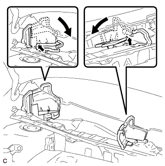
| 22. REMOVE COWL TOP PANEL OUTER (for Hatchback) |
Отсоедините зажимы и отогните правую водозащитную пластину и брызгозащитное уплотнение воздуховода отопителя № 1, как показано на рисунке.
Выверните 8 болтов и снимите наружную верхнюю панель кожуха.
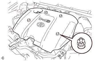
| 23. REMOVE NO. 1 ENGINE COVER |
Disengage the 4 pins and remove No. 1 engine cover sub-assembly.
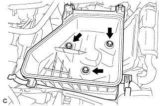
| 24. REMOVE AIR CLEANER CAP SUB-ASSEMBLY |
Disconnect the mass air flow meter connector.
Disconnect the No. 2 ventilation hose.
Disconnect the 2 clamps and band, and remove the air cleaner cap sub-assembly.
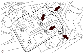
| 25. REMOVE AIR CLEANER FILTER ELEMENT SUB-ASSEMBLY |
| 26. REMOVE AIR CLEANER CASE SUB-ASSEMBLY |
Remove the 3 bolts and air cleaner case sub-assembly.
| 27. REMOVE BATTERY CARRIER |
Remove the 6 bolts and battery carrier.
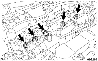
| 28. REMOVE NO. 1 GLOW PLUG CONNECTOR |
Remove the 5 screw grommets.
Remove the nut and disconnect the glow terminal.
Remove the 4 nuts and No. 1 glow plug connector.
| 29. REMOVE GLOW PLUG ASSEMBLY |
Using a deep socket wrench 10 mm, remove the 4 glow plugs.
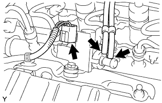
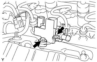
| 30. REMOVE VACUUM REGULATING VALVE ASSEMBLY |
Disconnect the vacuum regulating valve connector.
Disconnect the 2 vacuum hoses from the vacuum regulating valve.
Remove the 2 bolts and vacuum regulating valve.
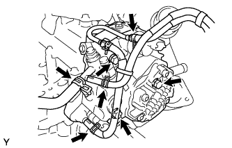
| 31. REMOVE EGR COOLER ASSEMBLY |
Disconnect the 2 water by-pass hoses.
Remove the bolt and 4 nuts, then remove the EGR cooler assembly.
Remove the 2 gaskets.
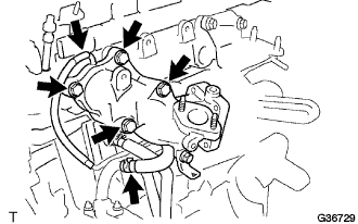
| 32. REMOVE EGR VALVE ASSEMBLY |
Disconnect the EGR valve connector and hose.
Remove the 2 nuts, then remove the EGR valve assembly.
Remove the gasket.
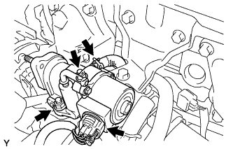
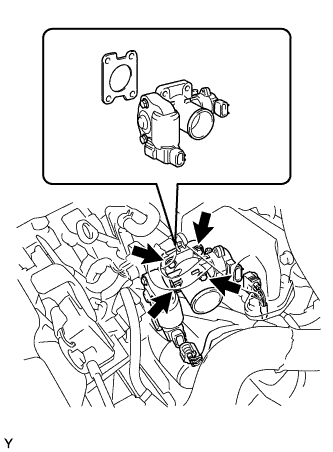
| 33. REMOVE DIESEL THROTTLE BODY ASSEMBLY |
Disconnect the throttle control motor connector.
Disconnect the throttle position sensor connector.
Remove the 4 bolts and remove the diesel throttle body and gasket.
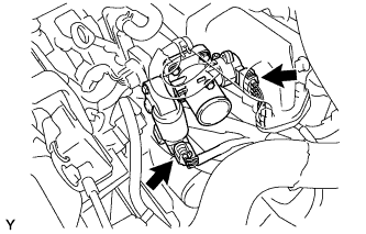
| 34. REMOVE INTAKE AIR CONNECTOR |
Disconnect the vacuum hose and the water hose.
Remove the 4 bolts and intake air connector.
| 35. REMOVE EGR PIPE CONNECTOR |
Remove the 3 bolts and EGR pipe connector.
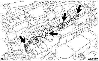
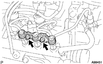
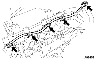
| 36. REMOVE NO. 1 INJECTION PIPE CLAMP |
Remove the 2 nuts, then remove the No. 1 injection pipe clamp.
| 37. REMOVE NO. 2 INJECTION PIPE CLAMP |
Remove the nut, then remove the No. 2 injection pipe clamp.
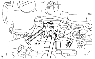
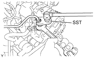
| 38. REMOVE NO. 1 INJECTION PIPE SUB-ASSEMBLY |
Using a wrench (13 mm), hold the injector steadily, and using SST, remove the injection pipe from the injector side.
- SST
- 09023-38401
Using SST, remove the injection pipe from the common rail side.
- SST
- 09023-38401
After removing the injection pipe, cover the common rail with vinyl tape and cover the injector inlet with a vinyl or plastic bag in order to prevent dust and foreign matter from entering.
| 39. REMOVE NO. 2 INJECTION PIPE SUB-ASSEMBLY |
Perform the same procedure as for No. 1 injection pipe sub-assembly.
- SST
- 09023-38401
| 40. REMOVE NO. 3 INJECTION PIPE SUB-ASSEMBLY |
Perform the same procedure as for No. 1 injection pipe sub-assembly.
- SST
- 09023-38401
| 41. REMOVE NO. 4 INJECTION PIPE SUB-ASSEMBLY |
Perform the same procedure as for No. 1 injection pipe sub-assembly.
- SST
- 09023-38401
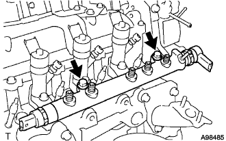
| 42. REMOVE NOZZLE LEAKAGE PIPE ASSEMBLY |
Remove the 5 retainer springs, then remove the nozzle leakage pipe.
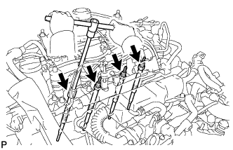
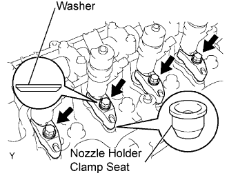
| 43. REMOVE INJECTOR ASSEMBLY |
- УКАЗАНИЕ:
- Each injector assembly has its own serial number. When replacing the injector assembly, store them in the correct order so that they can be returned to their original locations when reassembled.
- Arrange the injectors, clamps, washers, bolts and clamp seats in the correct order.
Remove the 4 bolts, 4 washers, 4 nozzle holder clamps and 4 nozzle holder clamp seats.
Disconnect the 4 injector connectors.
Remove the 4 injectors from the cylinder head.
Remove the 4 injection nozzle seats from the injector or cylinder head.
- ПРИМЕЧАНИЕ:
- When removing the injector, check that the injector nozzle seat is either attached to the injector, or remains in the cylinder head.
| 44. REMOVE FUEL INLET PIPE SUB-ASSEMBLY |
Using a wrench (17 mm), hold the supply pump steadily, and using SST, remove the fuel inlet pipe from the supply pump side.
- SST
- 09023-38401
Using SST, remove the fuel inlet pipe from the common rail side.
- SST
- 09023-38401
After removing the fuel inlet pipe, cover the common rail with vinyl tape and cover the injector inlet with a plastic bag in order to prevent dust and foreign matter from entering.
| 45. REMOVE COMMON RAIL ASSEMBLY |
- SST
- 09023-38401
Disconnect the 2 connectors.
Disconnect the fuel hose.
Remove the 2 bolts and common rail.
- ПРИМЕЧАНИЕ:
- Do not remove the fuel pressure sensor or fuel pressure regulator.
| 46. REMOVE SUPPLY PUMP ASSEMBLY |
Disconnect the 3 fuel hoses.
Disconnect the 2 connectors.
Remove the 3 bolts, then remove the supply pump.
Remove the supply pump drive coupling.
Remove the O-ring.
- ПРИМЕЧАНИЕ:
- When removing the supply pump, make sure that the drive coupling does not fall off, as it can be easily removed. If the drive coupling falls off, replace it with a new one.
| 47. REMOVE FRONT EXHAUST PIPE ASSEMBLY |
Remove the 2 bolts and 2 compression springs.
Remove the 2 bolts and 2 compression springs.
Remove the exhaust pipe supports, then remove the front exhaust pipe assembly.
| 48. REMOVE NO. 1 TURBO INSULATOR |
Remove the 3 bolts and No. 1 turbo insulator.
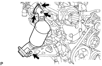
| 49. REMOVE EXHAUST MANIFOLD CONVERTER SUB-ASSEMBLY |
Remove the bolt, and separate the manifold support bracket.
Remove the 3 nuts and exhaust manifold converter.
Remove the gasket from the turbocharger.
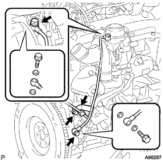
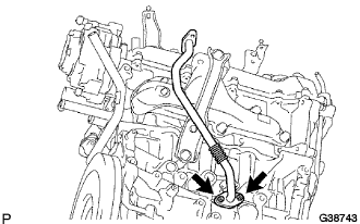
| 50. REMOVE TURBO OIL INLET PIPE |
Remove the wire harness clamp.
Remove the bolt.
Remove the 2 union bolts, oil inlet pipe and 4 gaskets.
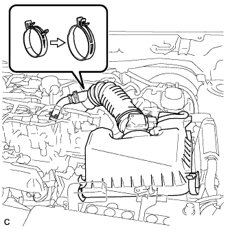
| 51. REMOVE NO. 1 AIR HOSE |
Loosen the 2 hose clamp bolts and remove intercooler No. 1 air hose.
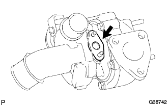
| 52. REMOVE TURBO CHARGER SUB-ASSEMBLY |
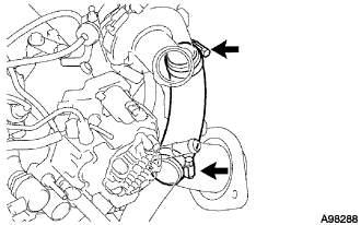
Remove the 2 nuts.
Disconnect the vacuum hose from the turbocharger.
Remove the 3 nuts and turbocharger.
Remove the gasket from the exhaust manifold.
Remove the gasket from the turbocharger.
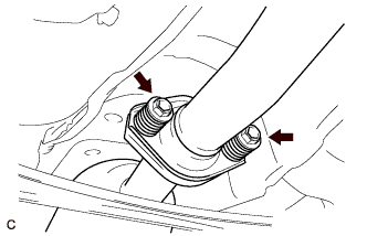
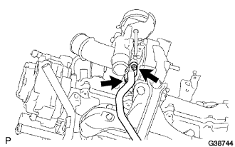
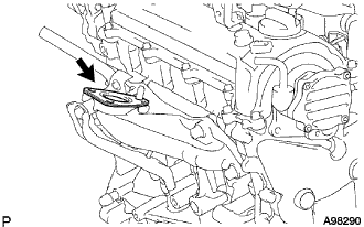
| 53. REMOVE TURBO OIL OUTLET PIPE |
Remove the 2 nuts and turbo oil outlet pipe.
Remove the gasket from the cylinder block.
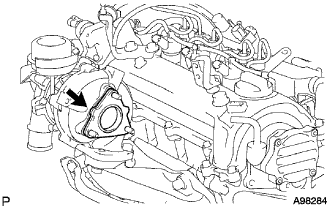
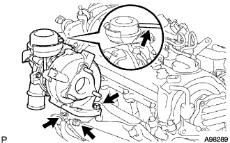
| 54. REMOVE EXHAUST MANIFOLD |
Remove the 2 bolts, then remove the manifold stay.
Remove the 2 bolts, then remove exhaust manifold heat insulator No. 1.
Remove the 5 nuts, then remove the exhaust manifold with turbocharger.
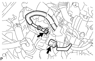
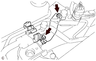
Remove the 3 bolts and 2 wire harness clamps, then separate the wire harness.
Loosen bolts A and B.
Remove the v-ribbed belt.
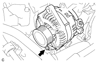
| 56. REMOVE GENERATOR ASSEMBLY |
Remove the terminal cap.
Remove the nut and disconnect the wire harness from terminal B.
Disconnect the generator connector.
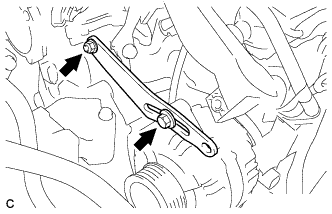
Remove the bolt, nut, and fan belt adjusting slider.
Remove the bolt and generator assembly.
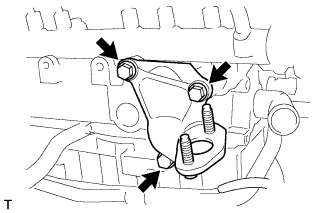
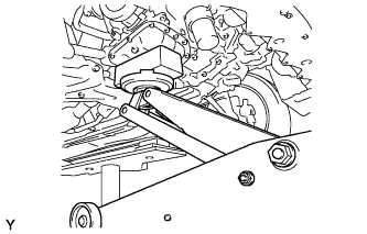
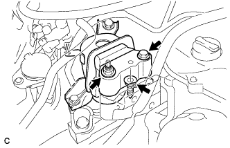
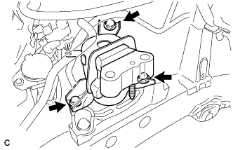
| 57. REMOVE ENGINE MOUNTING INSULATOR SUB-ASSEMBLY RH |
Support the engine with a jack and a wooden block as shown in the illustration.
Remove the bolt, nut, and air conditioner pipe bracket.
Remove the bolt, 2 nuts and engine mounting insulator RH from the engine mounting bracket.
Remove the 3 bolts and engine mounting insulator RH.
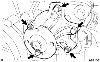
| 58. REMOVE WATER PUMP PULLEY |
Using SST, hold the water pump pulley.
- SST
- 09960-10010(09962-01000,09963-00700)
Remove the 4 bolts, then remove the water pump pulley.
| 59. REMOVE WATER PUMP ASSEMBLY |
Remove the 3 bolts and 2 nuts, then remove the water pump.
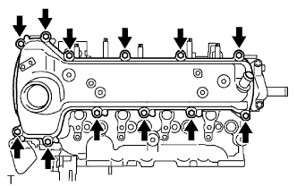
| 60. REMOVE CYLINDER HEAD COVER SUB-ASSEMBLY |
Remove the 12 bolts, then remove the cylinder head cover.
Remove the cylinder head cover gasket from the cylinder head cover.
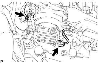
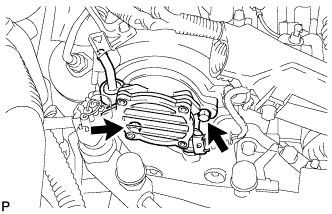
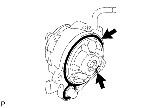
| 61. REMOVE VACUUM PUMP ASSEMBLY |
Сдвиньте фиксатор и отсоедините вакуумный шланг.
Отсоедините разъем датчика положения распредвала.
Вывыерните 2 болта и снимите вакуумный насос.
Снимите 2 кольцевых уплотнения с вакуумного насоса.
| 62. REMOVE CRANK SHAFT DAMPER SUB-ASSEMBLY |
Using SST, hold the crankshaft damper and loosen the crankshaft bolt.
- SST
- 09960-10010(09962-01000,09963-01000)
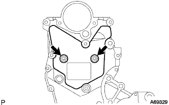
| 63. REMOVE NO. 2 TIMING CHAIN COVER |
Remove the 2 bolts and No. 2 timing chain cover.
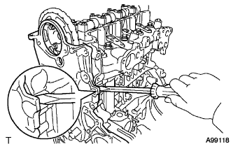
| 64. REMOVE OIL PUMP ASSEMBLY |
Remove the 16 bolts and nut.
Using a screwdriver with its tip wrapped in tape, remove the oil pump by prying out between the cylinder head and cylinder block.
- ПРИМЕЧАНИЕ:
- Be careful not to damage the contact surfaces of the oil pump assembly, cylinder head, and cylinder block.
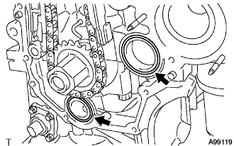
Remove the 2 O-rings from the cylinder block and oil pan.
Using a screwdriver with its tip wrapped in tape, remove the oil pump seal.
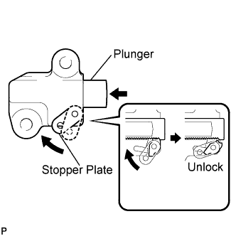
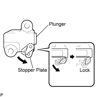
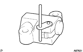
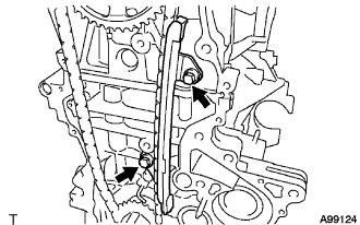
| 66. REMOVE NO. 1 CHAIN TENSIONER ASSEMBLY |
- ПРИМЕЧАНИЕ:
- Do not rotate the crankshaft with the chain tensioner removed.
Pull up the stopper plate to unlock the plunger.
Unlock the plunger and push it in to the end.
Pull down the stopper plate with the plunger pushed to the end to lock the plunger.
Insert a 2.5 mm (0.098 in.) diameter bar into the hole in the stopper plate with the plunger locked.
- УКАЗАНИЕ:
- If the stopper plate is not completely pulled down and a 2.5 mm (0.098 in.) diameter bar cannot be inserted, unlock and pull out the plunger slightly. The stopper plate will be completely pulled down and a 2.5 mm (0.098 in.) diameter bar can be inserted easily.
Remove the 2 bolts and No. 1 chain tensioner.
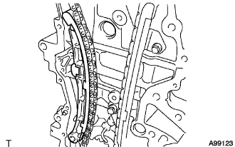
| 67. REMOVE CHAIN TENSIONER SLIPPER |
Remove the 2 bolts and No. 1 chain tensioner.
| 68. REMOVE NO. 1 CHAIN VIBRATION DAMPER |
Remove the 2 bolts and chain vibration damper.
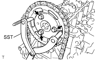
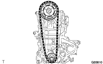
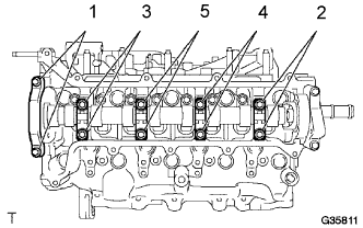
| 69. REMOVE CHAIN SUB-ASSEMBLY |
Using SST, hold the camshaft timing sprocket.
- SST
- 09960-10010(09962-01000,09963-01000)
Remove the 3 bolts, then remove the camshaft timing sprocket.
Remove the camshaft timing sprocket, crankshaft timing sprocket and chain together.
Remove the 10 bolts of the camshaft bearing caps in the sequence shown in the illustration, and then remove the 5 camshaft bearing caps.
- ПРИМЕЧАНИЕ:
- Using several steps, uniformly loosen the bolts while keeping the camshaft level.
- Do not remove camshaft beating cap No. 3.
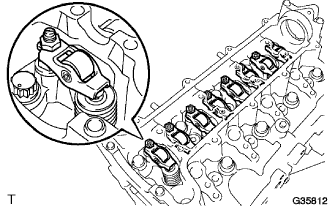
| 71. REMOVE NO. 1 VALVE ROCKER ARM SUB-ASSEMBLY |
Remove the 8 valve rocker arms from the cylinder head.
| 72. REMOVE OIL LEVEL GAUGE GUIDE |
Remove the oil level gauge from the oil level gauge guide.
Remove the bolt, then remove the oil level gauge guide.
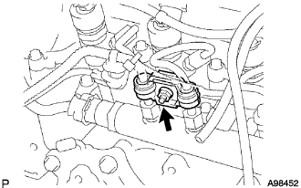
| 73. DISCONNECT MANIFOLD ABSOLUTE PRESSURE SENSOR HOSE |
Disconnect the turbo pressure sensor hose.
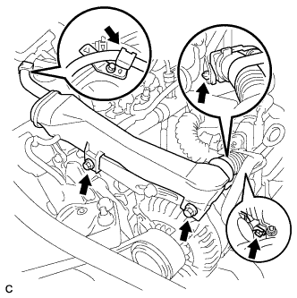
| 74. DISCONNECT NO. 1 RADIATOR HOSE |
Remove the clamp and disconnect the No. 1 radiator hose.
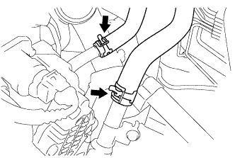
| 75. DISCONNECT HEATER INLET WATER HOSE |
Remove the clamp and disconnect the heater inlet water hose.
| 76. DISCONNECT HEATER OUTLET WATER HOSE |
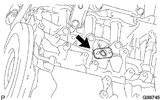
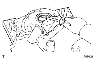
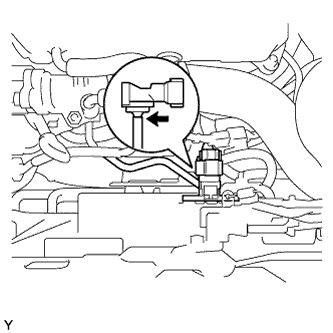
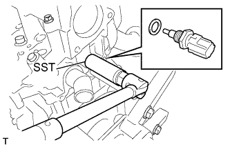
| 77. REMOVE ENGINE COOLANT TEMPERATURE SENSOR |
Using SST, remove the engine coolant temperature sensor.
- SST
- 09817-33190
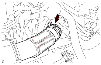
| 78. DISCONNECT OIL COOLER HOSE SUB-ASSEMBLY |
Remove the oil cooler hose sub-assembly.
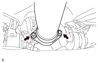
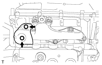
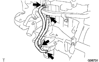
| 79. REMOVE NO. 1 WATER BY-PASS PIPE |
Remove the 2 nuts, 2 bolts, and No. 1 water by-pass pipe.
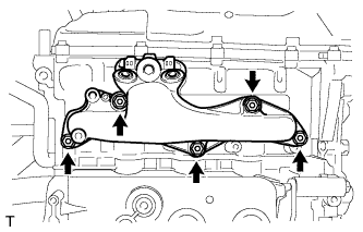
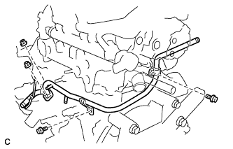
| 80. REMOVE CYLINDER HEAD SUB-ASSEMBLY |
Using several steps, loosen the 10 bolts in the sequence shown in the illustration, and then remove the bolts and washers.
- ПРИМЕЧАНИЕ:
- When removing the bolts, do not drop the washers into the engine.
- Removing the cylinder head bolts in the wrong order may cause damage to the cylinder head.
| 81. REMOVE CYLINDER HEAD GASKET |
Remove the cylinder head gasket.