Головка Блока Цилиндров -- Замена |
| 1. REPLACE INTAKE VALVE GUIDE BUSHING |
Heat the cylinder head to between 80 and 100°C (176 and 212°F).
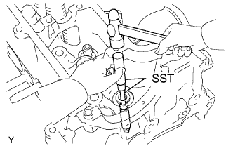 |
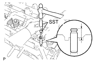
Using SST and a hammer, tap out the valve guide bushing to the combustion chamber side.
- SST
- 09201-10000
09950-70010
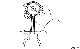
Using a caliper gauge, measure the bushing bore diameter of the cylinder head sub-assembly.
- Diameter:
- 10.985 to 11.006 mm (0.4325 to 0.4333 in.)
- УКАЗАНИЕ:
- If the bushing bore diameter is as specified, install the standard bushing.
- If the bushing bore diameter is not as specified, correct it to 11.035 to 11.056 mm (0.4345 to 0.4353 in.) and install the oversize bushing.
Bushing size Bushing bore diameter mm (in.) Standard Standard 10.985 to 11.006 (0.4325 to 0.4333) Over size (0.05) Over size 11.035 to 11.056 (0.4345 to 0.4353)
 |
Heat the cylinder head sub-assembly to between 80 and 100°C (176 and 212°F).
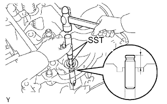
Using SST and a hammer, tap in a new valve guide bushing to the specified protrusion height.
- SST
- 09201-10000
09950-70010
- Protrusion height:
- 11.2 to 11.6 mm (0.441 to 0.457 in.)
 |
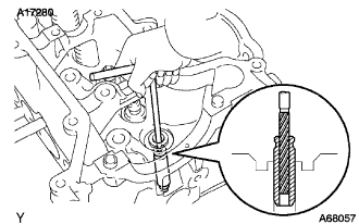
Using a reamer, ream the inside of the valve guide bushing to the specified oil clearance between the valve guide bushing and valve stem.
- Standard oil clearance:
- 0.025 to 0.060 mm (0.0010 to 0.0024 in.)
 |
| 2. REPLACE EXHAUST VALVE GUIDE BUSHING |
Heat the cylinder head to between 80 and 100°C (176 and 212°F).
 |
Using SST and a hammer, tap out the valve guide bushing to the combustion camber side.
- SST
- 09201-10000
09950-70010
Using a caliper gauge, measure the bushing bore diameter of the cylinder head sub-assembly.
- Diameter:
- 10.985 to 11.006 mm (0.4325 to 0.4333 in.)
- УКАЗАНИЕ:
- If the valve guide bushing bore diameter is as specified, install the standard valve guide bushing.
- If the valve guide bushing bore diameter is not as specified, correct it to 11.035 to 11.056 mm (0.4345 to 0.4353 in.) and install the oversize valve guide bushing.
Bushing size Bushing bore diameter mm (in.) Standard Standard 10.985 to 11.006 (0.4325 to 0.4333) Over size (0.05) Over size 11.035 to 11.056 (0.4345 to 0.4353)
|
Heat the cylinder head sub-assembly to between 80 and 100°C (176 and 212°F).
Using SST and a hammer, tap in a new valve guide bushing to the specified protrusion height.
- SST
- 09201-10000
09950-70010
- Protrusion height:
- 11.2 to 11.6 mm (0.441 to 0.457 in.)
 |
Using a reamer, ream the inside of the valve guide bushing to the specified oil clearance between the valve guide bushing and valve stem.
- Standard oil clearance:
- 0.030 to 0.065 mm (0.0012 to 0.0023 in.)
 |
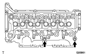
| 3. REPLACE RING PIN |
Remove the 2 ring pins indicated in the illustration.
 |
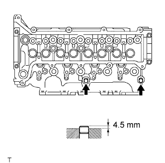
Using a plastic-faced hammer, tap in 2 new ring pins to the specified protrusion height.
- Protrusion height:
- 4.5 mm (0.177 in.)
 |
| 4. REPLACE STUD BOLT |
Remove the 6 bolts indicated in the illustration.
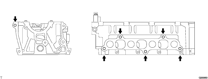
Install the 6 stud bolts in the positions shown in the illustration.
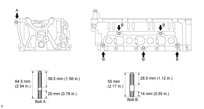
- Момент затяжки:
- Bolt A:
- 10 Н*м{102 кгс*см, 7.4 фунт-сила-футов}
- Bolt B:
- 22 Н*м{224 кгс*см, 16 фунт-сила-футов}