Зазор В Приводе Клапанов -- Регулировка |
| 1. DISCONNECT CABLE FROM NEGATIVE BATTERY TERMINAL |
| 2. REMOVE ENGINE UNDER COVER REAR RH |
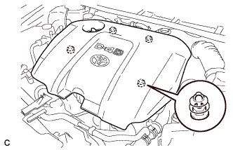
| 3. REMOVE NO. 1 ENGINE COVER |
Disengage the 4 pins and remove No. 1 engine cover sub-assembly.
 |
| 4. REMOVE CYLINDER HEAD COVER SUB-ASSEMBLY |
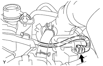
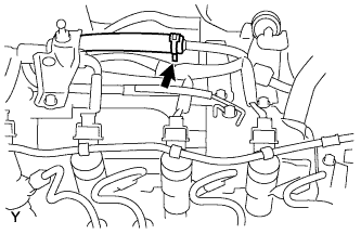
Disconnect the supply pump connector.
 |
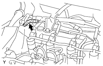
Disconnect the wire harness clamps shown in the illustration.
 |
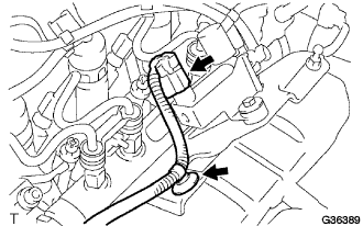
Disconnect the VSV connector shown in the illustration, and disengage the wire harness clamp shown in the illustration.
 |
Remove the screw grommet and nut, then separate the wire harness.
 |
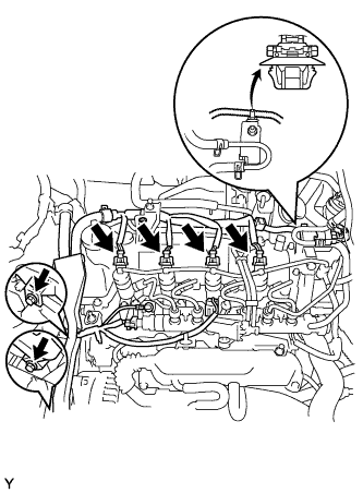
Disconnect the common rail connector.
Remove the 3 bolts and the 2 wire harness clamps shown in the illustration and disconnect the engine wire harness.
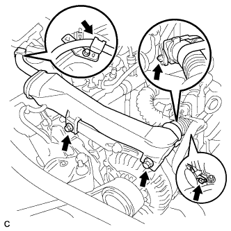 |
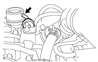
Disconnect the hose shown in the illustration.
 |
Disconnect the hose shown in the illustration.
 |
Disconnect the 3 vacuum hoses shown in the illustration.
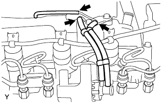 |
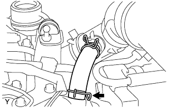
Disconnect the vacuum hose shown in the illustration.
 |
Disconnect the ventilation hose from the cylinder head.
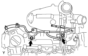
 |
Remove the 2 bolts, then remove the connector to vacuum reservoir tube.
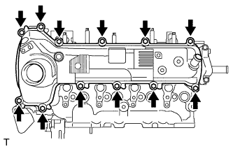
 |
Remove the 12 bolts, then remove the cylinder head cover.
 |
| 5. CHECK VALVE CLEARANCE |
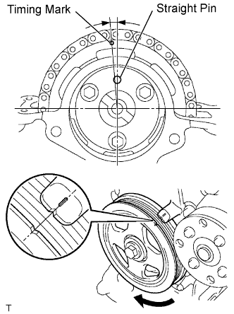
Set the No. 1 cylinder to TDC/Compression.
Turn the crankshaft pulley until the grooves of the crankshaft damper and oil pump are aligned.
Check that the timing mark of the camshaft timing sprocket is in the position shown in the illustration.
- УКАЗАНИЕ:
- If not, turn the crankshaft damper 1 revolution (360°) to align the timing mark and sprocket as above.
 |
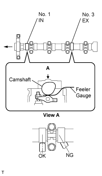
Check the valve clearance of the No. 1 cylinder exhaust valve and the No. 2 cylinder intake valve.
Using a feeler gauge, measure the clearance between the camshaft and valve rocker arm No. 1.
- Valve clearance (cold):
- 0.11 to 0.17 mm (0.004 to 0.007 in.) for intake
- 0.14 to 0.20 mm (0.006 to 0.008 in.) for exhaust
- ПРИМЕЧАНИЕ:
- Insert the feeler gauge into the center of the roller surface, parallel to the valve rocker arm No. 1.
- Do not apply excessive force to the valve adjusting screw when using adjusting tools such as SST and a screwdriver.
- УКАЗАНИЕ:
- If the clearance is not as specified, record the out-of-specification measurement, then adjust the valve clearance.
 |
Check the valve clearance of the No. 1 cylinder intake valve and the No. 3 cylinder exhaust valve.
Turn the crankshaft by a further 180° clockwise.
Using a feeler gauge, measure the clearance between the camshaft and valve rocker arm No. 1 as shown in the illustration.
- Valve clearance (cold):
- 0.11 to 0.17 mm (0.004 to 0.007 in.) for intake
- 0.14 to 0.20 mm (0.006 to 0.008 in.) for exhaust
- ПРИМЕЧАНИЕ:
- Insert the feeler gauge into the center of the roller surface, parallel to valve rocker arm No. 1.
- Do not apply excessive force to the valve adjusting screw with adjusting tools when measuring or adjusting.
- УКАЗАНИЕ:
- If the clearance is not as specified, record the out-of-specification measurement, then adjust the valve clearance.
 |
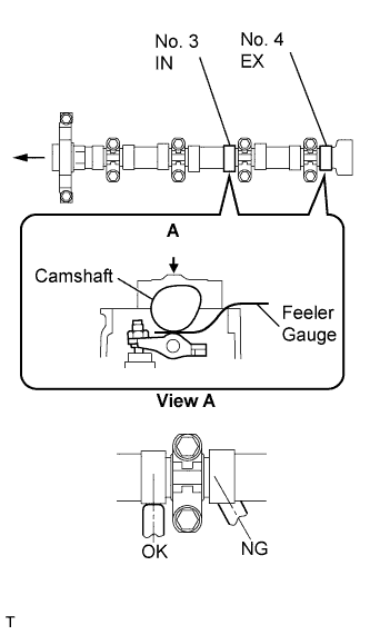
Check the valve clearances of the No. 3 cylinder intake valve and No. 4 cylinder exhaust valve.
Turn the crankshaft clockwise by a further 180°.
Using a feeler gauge, measure the clearance between the camshaft and valve rocker arm No. 1 as shown in the illustration.
- Valve clearance (cold):
- 0.11 to 0.17 mm (0.004 to 0.007 in.) for intake
- 0.14 to 0.20 mm (0.006 to 0.008 in.) for exhaust
 |
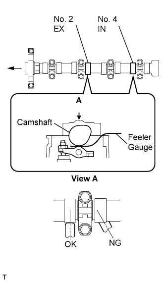
Check the valve clearances of the No. 2 cylinder intake valve and No. 4 cylinder intake valve.
Turn the crankshaft clockwise by a further 180°.
Using a feeler gauge, measure the clearance between the camshaft and valve rocker arm No. 1.
- Valve clearance (cold):
- 0.11 to 0.17 mm (0.004 to 0.007 in.) for intake
- 0.14 to 0.20 mm (0.006 to 0.008 in.) for exhaust
- ПРИМЕЧАНИЕ:
- Insert the feeler gauge into the center of the roller surface, parallel to valve rocker arm No. 1.
- Do not apply excessive force to the valve adjusting screw with adjusting tools when measuring or adjusting.
- УКАЗАНИЕ:
- If the clearance is not as specified, record the out-of-specification measurement, then adjust the valve clearance.
 |
| 6. ADJUST VALVE CLEARANCE |
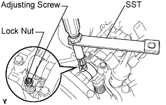 |
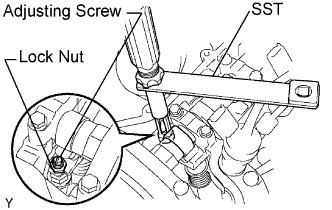
Using SST and a screwdriver, loosen the valve adjusting nut while keeping the valve adjusting screw in position.
- SST
- 09248-56010
Adjust valve clearance (intake side).
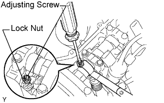
Insert a thickness gauge (0.14 mm (0.006 in.)) between the camshaft and valve rocker arm No. 1, and turn the valve adjusting screw to adjust it.
- Valve clearance (cold):
- 0.14 mm (0.006 in.)
Using SST and a screwdriver, tighten the valve adjusting nut while keeping the valve adjusting screw in position.
- Момент затяжки:
- With SST:
- 13 Н*м{133 кгс*см, 10 фунт-сила-футов}
- Without SST:
- 20 Н*м{204 кгс*см, 15 фунт-сила-футов}
 |
Adjust the valve clearance (exhaust side).
- Valve clearance (cold):
- 0.17 mm (0.007 in.)
- УКАЗАНИЕ:
- Perform the same procedure as for the intake valve clearance adjustment.
| 7. INSTALL CYLINDER HEAD COVER SUB-ASSEMBLY |
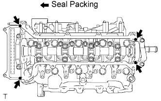
Apply seal packing to the 4 locations as shown in the illustration, then install the cylinder head cover.
- Seal packing:
- Toyota Genuine Seal Packing Black, Three Bond 1207B or equivalent
- ПРИМЕЧАНИЕ:
- Remove any oil from the contact surface.
- Install the cylinder head cover within 3 minutes, and tighten the bolts within 15 minutes of applying the seal packing.
 |
Temporarily tighten the cylinder head cover with the 12 bolts.
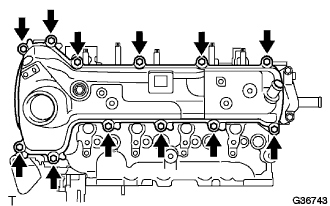 |
Tighten the 12 bolts to the specified torque as shown in the illustration.
- Момент затяжки:
- 13 Н*м{133 кгс*см, 10 фунт-сила-футов}
Install the connector to vacuum reservoir tube with the 2 bolts.
- Момент затяжки:
- 11 Н*м{112 кгс*см, 8 фунт-сила-футов}
|
Connect the ventilation hose to the cylinder head.
|
Connect the vacuum hose shown in the illustration.
|
Connect the 3 vacuum hoses shown in the illustration.
|
Connect the hose shown in the illustration.
|
Connect the hose shown in the illustration.
|
Install the 3 bolts and 2 wire harness clamps shown in the illustration, and connect the engine wire harness.
- Момент затяжки:
- Bolt A:
- 13 Н*м{131 кгс*см, 10 фунт-сила-футов}
- Bolt B:
- 11 Н*м{112 кгс*см, 8 фунт-сила-футов}
 |
Connect the common rail connector.
|
Install the wire harness with the screw grommet and the nut.
- Момент затяжки:
- 4.0 Н*м{41 кгс*см, 35 фунт-сила-дюймов}
Connect the VSV connector and wire harness clamp shown in the illustration.
|
Connect the wire harness clamp shown in the illustration.
|
Connect the supply pump connector.
|
| 8. CONNECT CABLE TO NEGATIVE BATTERY TERMINAL |
- Момент затяжки:
- 5.4 Н*м{55 кгс*см, 48 фунт-сила-дюймов}
| 9. INSTALL NO. 1 ENGINE COVER |
Fit the 4 retainers and install the No. 1 engine cover.
| 10. INSTALL ENGINE UNDER COVER REAR RH |