Двигатель. COROLLA, AURIS. ZZE150 ZRE151,152 NDE150
DESCRIPTION
WIRING DIAGRAM
INSPECTION PROCEDURE
READ VALUE OF INTELLIGENT TESTER (STARTER SIGNAL)
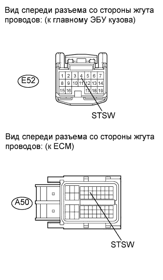
CHECK ECM (STSW TERMINAL VOLTAGE)
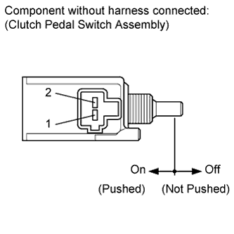
CHECK CLUTCH PEDAL SWITCH ASSEMBLY (INPUT VOLTAGE)
INSPECT CLUTCH PEDAL SWITCH ASSEMBLY
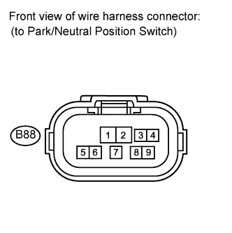
CHECK PARK/NEUTRAL POSITION SWITCH (INPUT VOLTAGE)
INSPECT PARK/NEUTRAL POSITION SWITCH
CHECK HARNESS AND CONNECTOR (ECM - MAIN BODY ECU)
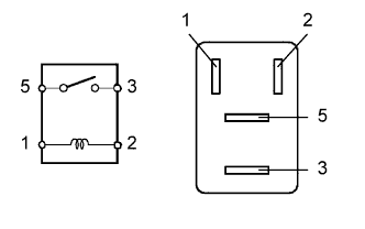
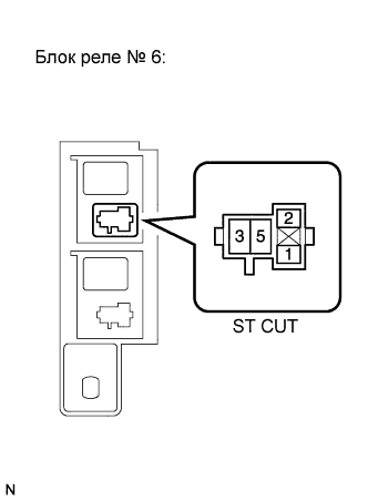
INSPECT ST CUT RELAY
CHECK HARNESS AND CONNECTOR (ST CUT RELAY - BODY GROUND)
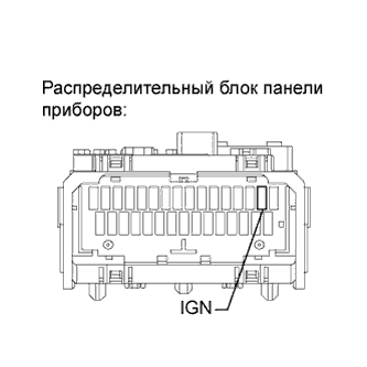
INSPECT IGN FUSE
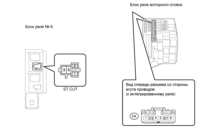
CHECK HARNESS AND CONNECTOR (ST CUT RELAY - IG2 RELAY)
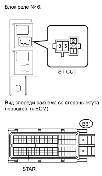
CHECK HARNESS AND CONNECTOR (ST CUT RELAY - ECM)
CHECK HARNESS AND CONNECTOR (ST CUT RELAY - MAIN BODY ECU)
CHECK HARNESS AND CONNECTOR (MAIN BODY ECU - CLUTCH PEDAL SWITCH ASSEMBLY)
CHECK HARNESS AND CONNECTOR (MAIN BODY ECU - PARK/NEUTRAL POSITION SWITCH)
CHECK ST RELAY (INPUT VOLTAGE)
INSPECT ST RELAY
CHECK HARNESS AND CONNECTOR (ST RELAY - BODY GROUND)
CHECK ST RELAY (INPUT VOLTAGE)
CHECK HARNESS AND CONNECTOR (ST RELAY - STARTER)
INSPECT STARTER
INSPECT FUSE (AM2 FUSE)
СИСТЕМА SFI - Цепь функции полуавтоматического запуска двигателя |
DESCRIPTION
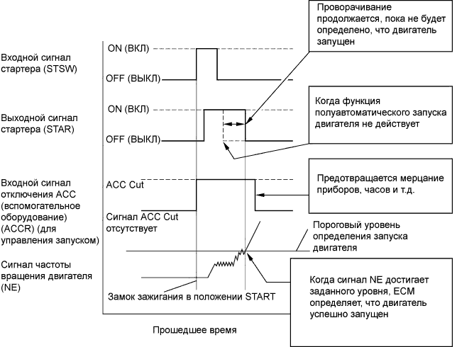
The cranking holding control system keeps energizing the ST relay after the ECM detects the starter signal (STSW signal) from the main body ECU until the ECM performs a judgment of "Engine started". Furthermore, the ECM outputs an accessory cut signal (ACCR signal) to the ACC relay during cranking to prevent flickering of the combination meter, clock, audio system, and other areas.When the ECM detects the STSW signal, the ECM outputs the starter relay drive signal (STAR signal) to the starter relay through the clutch pedal switch assembly, and then the engine is cranked. When the ECM receives a stable engine speed signal (NE signal) (more specifically, when the NE signal reaches a predetermined value), the ECM stops outputting the STAR signal. Also, the ECM monitors the ST relay operating conditions based on the STA terminal voltage status.
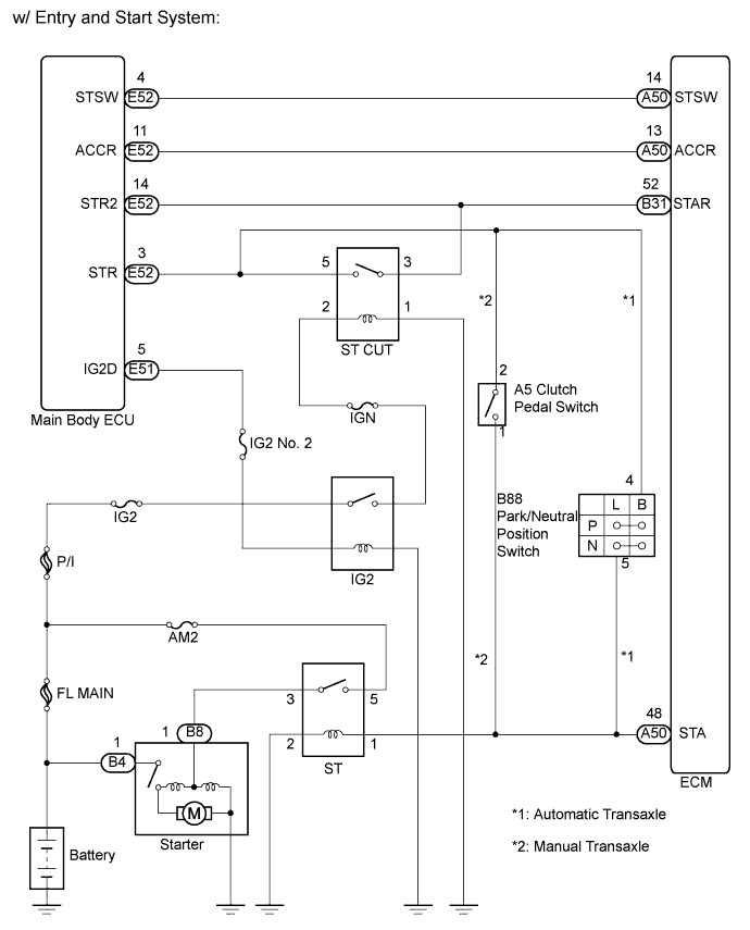
WIRING DIAGRAM
INSPECTION PROCEDURE
| 1.READ VALUE OF INTELLIGENT TESTER (STARTER SIGNAL) |
Connect the intelligent tester to the DLC3.
Turn the ignition switch on (IG) and turn the tester on.
Enter the following menu items: Powertrain / Engine and ECT / Data List / Starter Signal.
Check the result when the ignition switch is turned on (IG).
Check the result when the engine starts.
- OK:
Switch Condition
| Tester Display (Starter Signal)
|
Ignition switch on (IG)
| OFF
|
Engine starts
| ON
|
- Result:
| 2.CHECK ECM (STSW TERMINAL VOLTAGE) |
Disconnect the ECM connector.
Depress the clutch pedal fully (for manual transaxle).
Shift the shift lever to N position (for automatic transaxle).
Measure the voltage according to the value(s) in the table below.
- Standard voltage:
Tester Connection
| Switch Condition
| Specified Condition
|
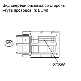
A50-14 (STSW) - Body ground
| Engine cranking
| 9 to 14 V
|
- УКАЗАНИЕ:
- The engine does not crank because the terminal is not connected.
- Result:
Result
| Proceed to
|
OK (Manual transaxle)
| A
|
OK (Automatic transaxle)
| B
|
NG
| C
|
Reconnect the ECM connector.
| 3.CHECK CLUTCH PEDAL SWITCH ASSEMBLY (INPUT VOLTAGE) |
Disconnect the clutch pedal switch assembly connector.
Measure the voltage according to the value(s) in the table below.
- Standard voltage:
Tester Connection
| Switch Condition
| Specified Condition
|
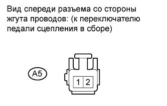
A5-2 - Body ground
| Engine cranking
| 9 to 14 V
|
- УКАЗАНИЕ:
- The engine does not crank because the terminal is not connected.
Reconnect the clutch pedal switch assembly connector.
| 4.INSPECT CLUTCH PEDAL SWITCH ASSEMBLY |
Disconnect the clutch pedal switch assembly connector.
Measure the resistance according to the value(s) in the table below.
- Standard resistance:
Tester Connection
| Switch Condition
| Specified Condition
|
1 - 2
| Pushed
| Below 1 Ω
|
1 - 2
| Not pushed
| 10 kΩ or higher
|
Reconnect the clutch pedal switch assembly connector.
| OK |
|
|
|
| REPAIR OR REPLACE HARNESS OR CONNECTOR (CLUTCH PEDAL SWITCH ASSEMBLY - ECM) |
|
| 5.CHECK PARK/NEUTRAL POSITION SWITCH (INPUT VOLTAGE) |
Disconnect the park/neutral position switch connector.
Measure the voltage according to the value(s) in the table below.
- Standard voltage:
Tester Connection
| Switch Condition
| Specified Condition
|
B88-4 - Body ground
| Engine cranking
| 9 to 14 V
|
- УКАЗАНИЕ:
- The engine does not crank because the terminal is not connected.
Reconnect the park/neutral position switch connector.
| 6.INSPECT PARK/NEUTRAL POSITION SWITCH |
Inspect the park/neutral position switch (See page Нажмите здесь).
| | REPLACE PARK/NEUTRAL POSITION SWITCH (FOR U341E AUTOMATIC TRANSAXLE) (Нажмите здесь) |
|
|
| OK |
|
|
|
| REPAIR OR REPLACE HARNESS OR CONNECTOR (PARK/NEUTRAL POSITION SWITCH - ECM) |
|
| 7.CHECK HARNESS AND CONNECTOR (ECM - MAIN BODY ECU) |
Disconnect the main body ECU connector.
Disconnect the ECM connector.
Measure the resistance according to the value(s) in the table below.
- Standard resistance:
Tester Connection
| Condition
| Specified Condition
|
E52-4 (STSW) - A50-14 (STSW)
| Always
| Below 1 Ω
|
E52-4 (STSW) or 50-14 (STSW) - Body ground
| Always
| 10 kΩ or higher
|
Reconnect the main body ECU connector.
Reconnect the ECM connector.
| | REPAIR OR REPLACE HARNESS OR CONNECTOR (ECM - MAIN BODY ECU) |
|
|
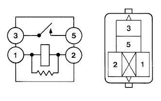
Remove the ST CUT relay from the No. 6 relay block.
Measure the resistance according to the value(s) in the table below.
- Standard resistance:
Tester Connection
| Condition
| Specified Condition
|
3 - 5
| Normal
| 10 kΩ or higher
|
3 - 5
| Apply the battery voltage between terminals 1 and 2
| Below 1 Ω
|
Reinstall the relay.
| 9.CHECK HARNESS AND CONNECTOR (ST CUT RELAY - BODY GROUND) |
Remove the ST CUT relay from the No. 6 relay block.
Measure the resistance according to the value(s) in the table below.
- Standard resistance:
Tester Connection
| Condition
| Specified Condition
|
ST CUT relay terminal 1 - Body ground
| Always
| Below 1 Ω
|
Reinstall the ST CUT relay.
| | REPAIR OR REPLACE HARNESS OR CONNECTOR (ST CUT RELAY - BODY GROUND) |
|
|
Remove the IGN fuse form the instrument panel junction block.
Measure the resistance according to the value(s) in the table below.
- Standard resistance:
Tester Connection
| Condition
| Specified Condition
|
IGN fuse
| Always
| Below 1 Ω
|
Reconnect the IGN fuse.
| 11.CHECK HARNESS AND CONNECTOR (ST CUT RELAY - IG2 RELAY) |
Remove the ST CUT relay from the No. 6 relay block.
Remove the integration relay from the engine room relay block.
Disconnect the integration relay connector.
Measure the resistance according to the value(s) in the table below.
- Standard resistance (Check for open):
Tester Connection
| Condition
| Specified Condition
|
1A-4 - ST CUT relay terminal 2
| Always
| Below 1 Ω
|
- Standard resistance (Check for short):
Tester Connection
| Condition
| Specified Condition
|
1A-4 or ST CUT relay terminal 2 - Body ground
| Always
| 10 kΩ or higher
|
Reinstall the ST CUT relay.
Reconnect the integration relay connector.
Reinstall the integration relay.
| | REPAIR OR REPLACE HARNESS OR CONNECTOR (ST CUT RELAY - IG2 RELAY) |
|
|
| 12.CHECK HARNESS AND CONNECTOR (ST CUT RELAY - ECM) |
Disconnect the ECM connector.
Remove the ST CUT relay from the No. 6 relay block.
Measure the resistance according to the value(s) in the table below.
- Standard resistance (Check for open):
Tester Connection
| Condition
| Specified Condition
|
ST CUT relay terminal 3 - B31-52 (STAR)
| Always
| Below 1 Ω
|
- Standard resistance (Check for short):
Tester Connection
| Condition
| Specified Condition
|
ST CUT relay terminal 3 or B31-52 (STAR) - Body ground
| Always
| 10 kΩ or higher
|
Reconnect the ECM connector.
Reinstall the ST CUT relay.
| | REPAIR OR REPLACE HARNESS OR CONNECTOR (ST CUT RELAY - ECM) |
|
|
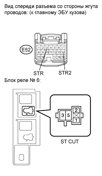
| 13.CHECK HARNESS AND CONNECTOR (ST CUT RELAY - MAIN BODY ECU) |
Disconnect the main body ECU connector.
Remove the ST CUT relay from the No. 6 relay block.
Measure the resistance according to the value(s) in the table below.
- Standard resistance (Check for open):
Tester Connection
| Condition
| Specified Condition
|
ST CUT relay terminal 3 - E52-14 (STR2)
| Always
| Below 1 Ω
|
ST CUT relay terminal 5 - E52-3 (STR)
| Always
| Below 1 Ω
|
- Standard resistance (Check for short):
Tester Connection
| Condition
| Specified Condition
|
ST CUT relay terminal 3 or E52-14 (STR2) - Body ground
| Always
| 10 kΩ or higher
|
ST CUT relay terminal 5 or E52-3 (STR) - Body ground
| Always
| 10 kΩ or higher
|
Reconnect the main body ECU connector.
Reinstall the ST CUT relay.
- Result:
Result
| Proceed to
|
OK (Manual transaxle)
| A
|
OK (Automatic transaxle)
| B
|
NG
| C
|
| |
|
| | REPAIR OR REPLACE HARNESS OR CONNECTOR (ST CUT RELAY - MAIN BODY ECU) |
|
|
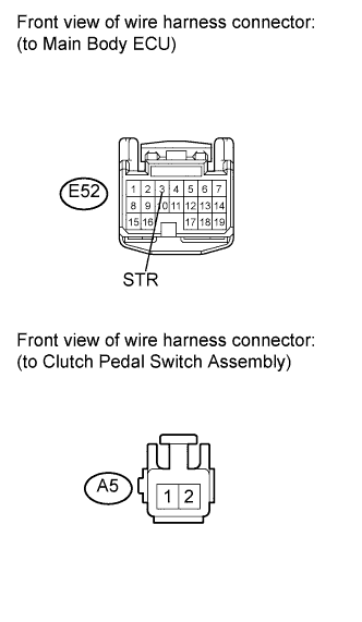
| 14.CHECK HARNESS AND CONNECTOR (MAIN BODY ECU - CLUTCH PEDAL SWITCH ASSEMBLY) |
Disconnect the main body ECU connector.
Disconnect the clutch pedal switch assembly connector.
Measure the resistance according to the value(s) in the table below.
- Standard resistance (Check for open):
Tester Connection
| Condition
| Specified Condition
|
E52-3 (STR) - A5-2
| Always
| Below 1 Ω
|
- Standard resistance (Check for short):
Tester Connection
| Condition
| Specified Condition
|
E52-3 (STR) or A5-2 - Body ground
| Always
| 10 kΩ or higher
|
Reconnect the main body ECU connector.
Reconnect the clutch pedal switch assembly connector.
| | REPAIR OR REPLACE HARNESS OR CONNECTOR (MAIN BODY ECU - CLUTCH PEDAL SWITCH ASSEMBLY) |
|
|
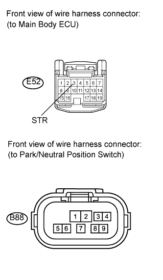
| 15.CHECK HARNESS AND CONNECTOR (MAIN BODY ECU - PARK/NEUTRAL POSITION SWITCH) |
Disconnect the main body ECU connector.
Disconnect the park/neutral position switch connector.
Measure the resistance according to the value(s) in the table below.
- Standard resistance (Check for open):
Tester Connection
| Condition
| Specified Condition
|
E52-3 (STR) - B88-4
| Always
| Below 1 Ω
|
- Standard resistance (Check for short):
Tester Connection
| Condition
| Specified Condition
|
E52-3 (STR) or B88-4 - Body ground
| Always
| 10 kΩ or higher
|
Reconnect the main body ECU connector.
Reconnect the park/neutral position switch connector.
| | REPAIR OR REPLACE HARNESS OR CONNECTOR (MAIN BODY ECU - PARK/NEUTRAL POSITION SWITCH) |
|
|
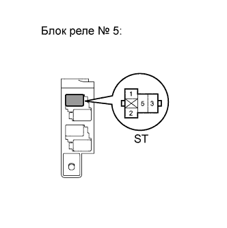
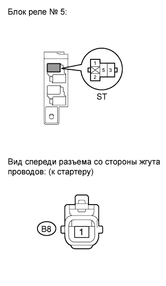
| 16.CHECK ST RELAY (INPUT VOLTAGE) |
Remove the ST relay from the No. 5 relay block.
Measure the voltage according to the value(s) in the table below.
- Standard voltage:
Tester Connection
| Switch Condition
| Specified Condition
|
ST relay terminal 1 - Body ground
| Engine cranking
| 9 to 14 V
|
- УКАЗАНИЕ:
- The engine does not crank because the terminal is not connected.
Reinstall the ST relay from the No. 5 relay block.
| | REPAIR OR REPLACE HARNESS OR CONNECTOR (ECM - ST RELAY) |
|
|
Remove the ST relay from the No. 5 relay block.
Measure the resistance according to the value(s) in the table below.
- Standard resistance:
Tester Connection
| Condition
| Specified Condition
|
3 - 5
| Normal
| 10 kΩ or higher
|
3 - 5
| Apply the battery voltage between terminals 1 and 2
| Below 1 Ω
|
Reinstall the ST relay.
| 18.CHECK HARNESS AND CONNECTOR (ST RELAY - BODY GROUND) |
Remove the ST relay from the No. 5 relay block.
Measure the resistance according to the value(s) in the table below.
- Standard resistance:
Tester Connection
| Condition
| Condition
|
ST relay terminal 2 - Body ground
| Always
| Below 1 Ω
|
Reinstall the ST relay.
| | REPAIR OR REPLACE HARNESS OR CONNECTOR (ST RELAY - BODY GROUND) |
|
|
| 19.CHECK ST RELAY (INPUT VOLTAGE) |
Remove the ST relay from the No. 5 relay block.
Measure the voltage according to the value(s) in the table below.
- Standard voltage:
Tester Connection
| Switch Condition
| Specified Condition
|
ST relay terminal 5 - Body ground
| Ignition switch on (IG)
| 9 to 14 V
|
Reinstall the ST relay.
| 20.CHECK HARNESS AND CONNECTOR (ST RELAY - STARTER) |
Remove the ST relay from the No. 5 relay block.
Disconnect the starter connector.
Measure the resistance according to the value(s) in the table below.
- Standard resistance (Check for open):
Tester Connection
| Condition
| Specified Condition
|
ST relay terminal 3 - B8-1
| Always
| Below 1 Ω
|
- Standard resistance (Check for short):
Tester Connection
| Condition
| Specified Condition
|
ST relay terminal 3 or B8-1 - Body ground
| Always
| 10 kΩ or higher
|
Reinstall the ST relay.
Reconnect the starter connector.
| | REPAIR OR REPLACE HARNESS OR CONNECTOR (ST RELAY STARTER) |
|
|
Inspect the starter (See page Нажмите здесь).
| OK |
|
|
|
| REPAIR OR REPLACE HARNESS OR CONNECTOR (BATTERY - STARTER) |
|
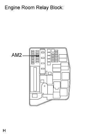
| 22.INSPECT FUSE (AM2 FUSE) |
Remove the AM2 fuse from the engine room relay block.
Measure the resistance according to the value(s) in the table below.
- Standard resistance:
Tester Connection
| Condition
| Specified Condition
|
AM2 fuse
| Always
| Below 1 Ω
|
Reinstall the AM2 fuse.
| OK |
|
|
|
| REPAIR OR REPLACE HARNESS OR CONNECTOR (BATTERY - ST RELAY) |
|