CHECK CONNECTION BETWEEN INTELLIGENT TESTER AND ECM
CHECK MIL (ACCELERATOR PEDAL POSITION SENSOR)
CHECK MIL (DIFFERENTIAL PRESSURE SENSOR)
CHECK MIL (FUEL PRESSURE SENSOR)
CHECK MIL (EGR VALVE POSITION SENSOR)
CHECK MIL (THROTTLE POSITION SENSOR)
CHECK MIL (DIESEL TURBO PRESSURE SENSOR)
CHECK HARNESS AND CONNECTOR (EACH SENSOR - BODY GROUND)
СИСТЕМА ECD - Выходная цепь VC |
DESCRIPTION
The ECM constantly generates 5 V power from the battery voltages supplied to the +B (BATT) terminal to operate the microprocessor. The ECM also provides this power to the sensors through the VC output circuit.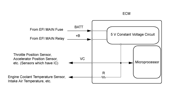
When the VC circuit is shorted, the microprocessor in the ECM and sensors that are supplied with power through the VC circuit are deactivated because the power is not supplied from the VC circuit. Under this condition, the system does not start up and the MIL does not illuminate even if the system malfunctions.
- УКАЗАНИЕ:
- Under normal conditions, the MIL is illuminated for several seconds when the ignition switch is first turned on (IG). The MIL goes off when the engine is started.
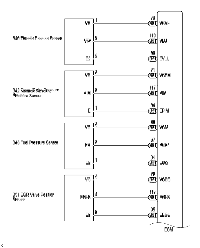
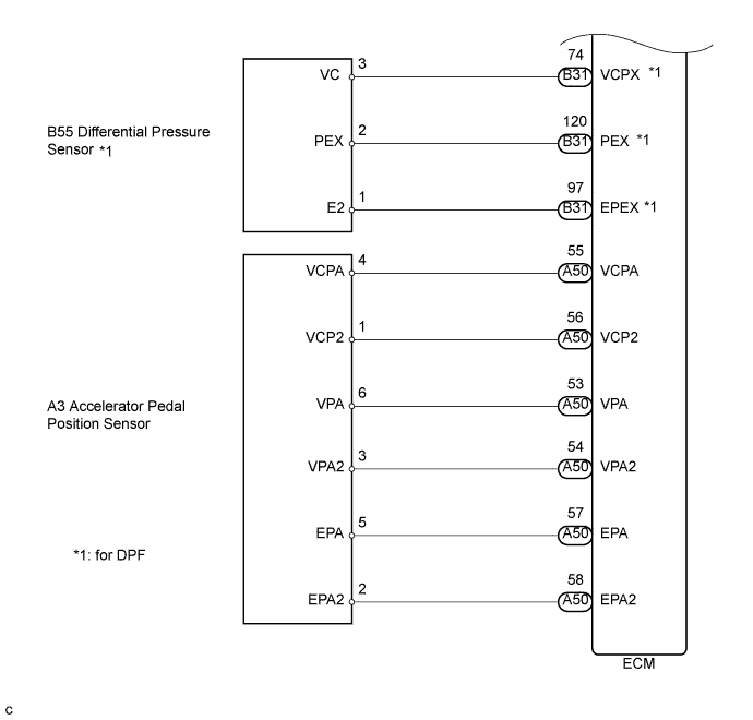
WIRING DIAGRAM
INSPECTION PROCEDURE
- ПРИМЕЧАНИЕ:
- After replacing the ECM, the new ECM needs registration (See page Нажмите здесь) and initialization (See page Нажмите здесь).
| 1.CHECK MIL CONDITION |
Check that the Malfunction Indicator Lamp (MIL) lights up when turning the ignition switch on (IG).
- OK:
- The MIL lights up.
|
| ||||
| OK | ||
| ||
| 2.CHECK CONNECTION BETWEEN INTELLIGENT TESTER AND ECM |
Connect the intelligent tester to the DLC3.
Turn the ignition switch on (IG) and turn the tester on.
Check the communication between the tester and ECM.
- Result:
Result Proceed to Communication is possible A Communication is not possible B
|
| ||||
| B | |
| 3.CHECK MIL (ACCELERATOR PEDAL POSITION SENSOR) |
Disconnect the accelerator pedal position sensor connector.
Turn the ignition switch on (IG).
Check the MIL.
- Result:
Result Proceed to MIL illuminates A MIL does not illuminate B
Reconnect the accelerator pedal position sensor connector.
|
| ||||
| B | |
| 4.CHECK MIL (DIFFERENTIAL PRESSURE SENSOR) |
- УКАЗАНИЕ:
- For except DPF, proceed to step 5.
Disconnect the differential pressure sensor connector.
Turn the ignition switch on (IG).
Check the MIL.
- Result:
Result Proceed to MIL illuminates A MIL does not illuminate B
Reconnect the differential pressure sensor connector.
|
| ||||
| B | |
| 5.CHECK MIL (FUEL PRESSURE SENSOR) |
Disconnect the fuel pressure sensor connector.
Turn the ignition switch on (IG).
Check the MIL.
- Result:
Result Proceed to MIL illuminates A MIL does not illuminate B
Reconnect the fuel pressure sensor connector.
|
| ||||
| B | |
| 6.CHECK MIL (EGR VALVE POSITION SENSOR) |
Disconnect the EGR valve position sensor connector.
Turn the ignition switch on (IG).
Check the MIL.
- Result:
Result Proceed to MIL illuminates A MIL does not illuminate B
Reconnect the EGR valve position sensor connector.
|
| ||||
| B | |
| 7.CHECK MIL (THROTTLE POSITION SENSOR) |
Disconnect the throttle position sensor connector.
Turn the ignition switch on (IG).
Check the MIL.
- Result:
Result Proceed to MIL illuminates A MIL does not illuminate B
Reconnect the throttle position sensor connector.
|
| ||||
| B | |
| 8.CHECK MIL (DIESEL TURBO PRESSURE SENSOR) |
Disconnect the diesel turbo pressure sensor connector.
Turn the ignition switch on (IG).
Check the MIL.
- Result:
Result Proceed to MIL illuminates A MIL does not illuminate B
Reconnect the diesel turbo pressure sensor connector.
|
| ||||
| B | |
| 9.CHECK HARNESS AND CONNECTOR (EACH SENSOR - BODY GROUND) |
Disconnect the accelerator pedal position sensor connector.
Disconnect the differential pressure sensor connector (for DPF).
Disconnect the fuel pressure sensor connector.
Disconnect the EGR valve position sensor connector.
Disconnect the throttle position sensor connector.
Disconnect the diesel turbo pressure sensor connector.
Disconnect the ECM connectors.
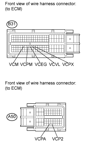 |
Measure the resistance according to the value(s) in the table below.
- Standard resistance:
Tester Connection Condition Specified Condition A50-55 (VCPA) - Body ground Always 10 kΩ or higher A50-56 (VCP2) - Body ground Always 10 kΩ or higher B31-74 (VCPX) - Body ground Always 10 kΩ or higher B31-69 (VCM) - Body ground Always 10 kΩ or higher B31-72 (VCEG) - Body ground Always 10 kΩ or higher B31-73 (VCVL) - Body ground Always 10 kΩ or higher B31-71 (VCPM) - Body ground Always 10 kΩ or higher
Reconnect the accelerator pedal position sensor connector.
Reconnect the differential pressure sensor connector (for DPF).
Reconnect the fuel pressure sensor connector.
Reconnect the EGR valve position sensor connector.
Reconnect the throttle position sensor connector.
Reconnect the diesel turbo pressure sensor connector.
Reconnect the ECM connectors.
|
| ||||
| OK | ||
| ||