Воздухозаборная Система -- Проверка Без Снятия С Автомобиля |
| 1. INSPECT INTAKE SYSTEM |
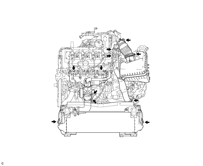
Check that there is no air leakage at the points shown in the illustration.
| 2. CHECK INTAKE AIR CONTROL SYSTEM |
Check for leakage or clogging between the air cleaner housing and turbocharger inlet and between the turbocharger outlet and cylinder head.
Condition Operation Clogged air cleaner Clean or replace element Hoses collapsed or deformed Repair or replace Leakage from connections Check each connection and repair Cracks in components Check and replace
| 3. CHECK EXHAUST SYSTEM |
Check for leakage or clogging between the cylinder head and turbocharger inlet and between the turbocharger outlet and exhaust pipe.
Condition Operation Deformed components Repair or replace Foreign material in passages Remove Leakage from components Repair or replace Cracks in components Check and replace
| 4. CHECK TURBOCHARGING PRESSURE |
Warm up the engine.
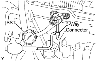
Using a 3-way connector, connect SST (turbocharger pressure gauge) to the hose leading to the intake air connector.
- SST
- 09992-00242
 |
While depressing the clutch pedal, fully depress the accelerator pedal. Measure the turbocharging pressure at maximum speed (5100 to 5250 rpm).
- Standard pressure:
- 53 to 61 kPa (0.54 to 0.6 kgf/cm2, 7.7 to 8.8 psi)
- If the pressure is less than the standard value, check both the intake air and exhaust systems for leakage. If there is no leakage, check if the actuator hose has been disconnected. If it has not, check the turbocharger.
- If the pressure is greater than the standard value, check if the actuator hose has been disconnected or cracked. If it has not, check the turbocharger.
| 5. CHECK TURBOCHARGER SUB-ASSEMBLY |
- ПРЕДОСТЕРЕЖЕНИЕ:
- Wear protective gloves to prevent injuries and burns when checking the turbocharger.
- The engine compartment becomes hot when the engine is running.
Remove the No. 1 engine cover (See page Нажмите здесь).
Remove the 2 bolts and No. 1 turbo insulator (See page Нажмите здесь).
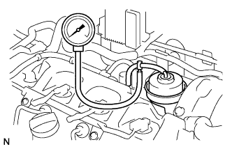
Using a 3-way connector, connect a vacuum gauge between the actuator and VRV.
 |
Warm up the engine.
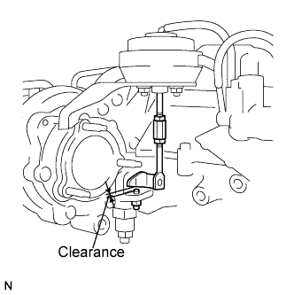
Measure the clearance between the stopper bolt and arm.
- Standard clearance:
Engine Condition Specified Condition Stopped 3 to 5 mm (0.118 to 0.197 in.) Idling 0.2 to 0.8 mm (0.0078 to 0.0314 in.)
 |
Measure the actuator pressure.
- Standard pressure:
Engine Condition Specified Condition Stopped 0 kPa (0 kgf/cm2, 0 psi) Idling 43 kPa (0.43 kgf/cm2, 6.2 psi)
Check the operation of the arm.
Check that the clearance between the stopper bolt and arm is 0.2 to 0.8 mm (0.0078 to 0.0314 in.) when the engine is idling.
When fully depressing the accelerator pedal, check that the arm moves toward the fully closed position and then toward the fully open position.
Install the No. 1 turbo insulator with the 2 bolts (See page Нажмите здесь).
Install the No. 1 engine cover (See page Нажмите здесь).