Блок Цилиндров -- Повторная Сборка |
| 1. INSTALL PISTON WITH PIN SUB-ASSEMBLY |
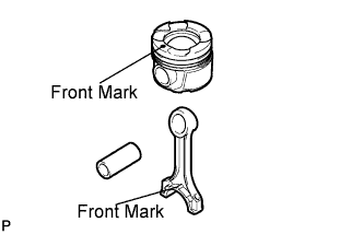
Assemble the piston and connecting rod.
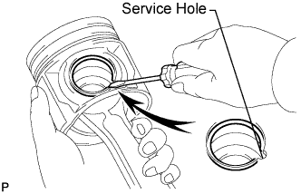
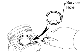
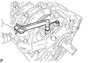
Using a screwdriver, install a new snap ring at one end of the piston pin hole.
Gradually heat the piston to approximately 80 to 90°C (176 to 194°F).
Coat the piston pin with engine oil.
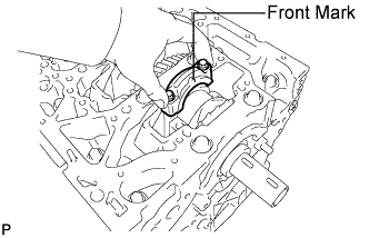
Align the front marks of the piston and connecting rod, and push in the piston pin with your thumb.
- УКАЗАНИЕ:
- The piston and pin are a matched set.
Using a screwdriver, install a new snap ring at the other end of the piston pin hole.
- УКАЗАНИЕ:
- Make sure that the 2 snap rings are securely installed into the grooves.
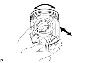
Move the connecting rod back and forth on the piston pin. Check the fitting condition.
Rotate the piston back and forth on the piston pin. Check the fitting condition.
 |
| 2. INSTALL PISTON RING SET |
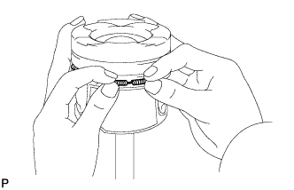
Install the oil ring expander by hand.
 |
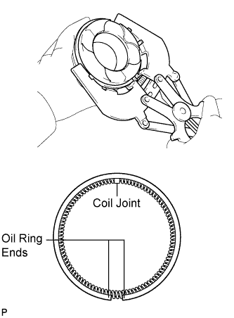
Using a piston ring expander, install the oil ring rail as shown in the illustration.
 |
Using a piston ring expander, install the 2 compression rings so that the painted marks are positioned as shown in the illustration.
- УКАЗАНИЕ:
- Install the No. 1 compression ring with the code mark (1T) facing upward.
- Install the No. 2 compression ring with the code mark (2FTE) facing upward.
 |
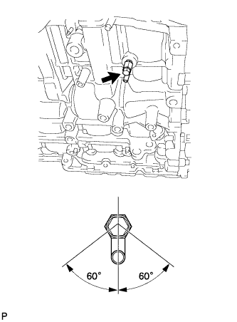
| 3. INSTALL CYLINDER BLOCK WATER DRAIN COCK SUB-ASSEMBLY |
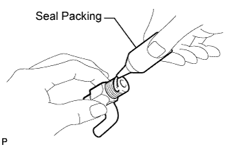
Apply seal packing around the drain cock.
- Seal packing:
- Toyota Genuine Seal Packing 1282B, Three Bond 1282B or equivalent
 |
Install the cylinder block water drain cock.
Temporarily install the drain cock.
- Момент затяжки:
- 20 Н*м{204 кгс*см, 15 фунт-сила-футов}
Within one full rotation, tighten the drain cock to the angle shown in the illustration.
- Момент затяжки:
- 80 Н*м{816 кгс*см, 59 фунт-сила-футов}or lower
- ПРИМЕЧАНИЕ:
- Do not loosen the drain cock to adjust it. If an adjustment is necessary, remove the drain cock and reinstall it.
| 4. INSTALL NO. 1 CRANKSHAFT POSITION SENSOR PLATE |
Install the sensor plate by fitting the straight pin of the crankshaft into the hole on the sensor plate.
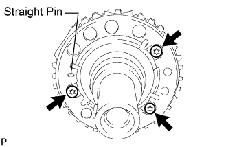 |
Using a T30 "TORX" socket wrench, install the 3 bolts.
- Момент затяжки:
- 10.5 Н*м{107 кгс*см, 8 фунт-сила-футов}
- ПРИМЕЧАНИЕ:
- Make sure to confirm that the sensor plate is not slanted.
| 5. INSTALL OIL REFLECTOR PLATE |
Using a 5 mm hexagon wrench, install the 3 oil reflector plates with the 3 bolts.
- Момент затяжки:
- 9.0 Н*м{92 кгс*см, 80 фунт-сила-дюймов}
 |
| 6. INSTALL NO. 1 OIL NOZZLE SUB-ASSEMBLY |
Using a 5 mm hexagon wrench, install the 4 oil nozzles with the 4 bolts.
- Момент затяжки:
- 9.0 Н*м{92 кгс*см, 80 фунт-сила-дюймов}
 |
| 7. INSTALL NO. 2 CRANKSHAFT BEARING |
- ПРИМЕЧАНИЕ:
 |
- Do not apply engine oil to the bearing's contact area and backside.
Clean the main journal, and both surfaces of the bearing.
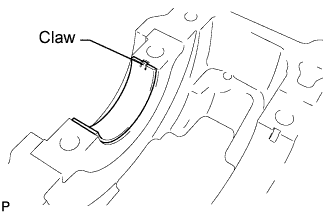
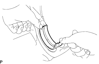
Align the bearing claw with the claw groove of the crankshaft bearing cap, and push in the 5 No. 2 crankshaft bearings.
| 8. INSTALL CRANKSHAFT BEARING |
 |
- ПРИМЕЧАНИЕ:
- Do not apply engine oil to the bearing's contact area and backside.
Clean the main journal, and both surfaces of the bearing.
Align the bearing claw groove of the cylinder block, and push in the 5 crankshaft bearings.
| 9. INSTALL CRANKSHAFT UPPER THRUST WASHER |
Apply engine oil to the crankshaft bearings, then place the crankshaft on the cylinder block.
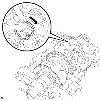 |
Push the crankshaft in one direction and install one thrust washer to the No. 4 journal position with the oil groove facing outward.
Push the crankshaft in the opposite direction and install the other thrust washer to the No. 4 journal position with the oil groove facing outward.
| 10. INSTALL CRANKSHAFT |
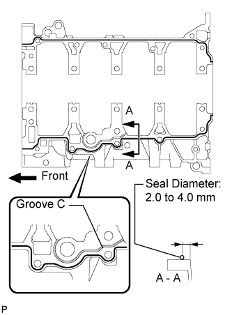
Apply seal packing in a continuous bead as shown in the illustration.
- Seal packing:
- Toyota Genuine Seal Packing Black, Three Bond 1207B or equivalent
- Seal diameter:
- 2.0 to 4.0 mm (0.078 to 0.157 in.)
- ПРИМЕЧАНИЕ:
- Remove any oil from the contact surface.
- Install the crankcase within 3 minutes after applying seal packing.
- Do not start the engine for at least 4 hours after the installation.
- Do not apply seal packing in groove C.
 |
Apply engine oil to the crankshaft No. 2 bearings, then place the crankshaft bearing cap on the cylinder block.
Apply a light coat of engine oil to the threads and under the heads of the crankshaft bearing cap bolts.
Install the crankshaft bearing cap bolts.
- УКАЗАНИЕ:
- The main bearing cap bolts are tightened as described in "Step 1" and "Step 2" below.
- If any bolt is broken or deformed, replace it.
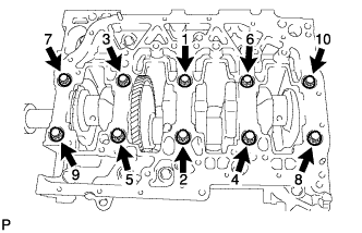 |
Step 1:
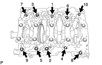
Install and uniformly tighten the 10 main bearing cap bolts in the sequence shown in the illustration.
- Момент затяжки:
- 60 Н*м{612 кгс*см, 44 фунт-сила-футов}
- УКАЗАНИЕ:
- If a main bearing cap bolt does not meet the torque specification, replace the main bearing cap bolts.
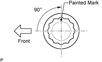
Step 2:
Mark the front of the bearing cap bolts with paint.
Retighten the bearing cap bolts by 90° as shown.
Check that the painted marks are now at a 90° angle to the front.
 |
Install and uniformly tighten the 10 bolts in several passes in the sequence shown in the illustration.
- Момент затяжки:
- 18 Н*м{184 кгс*см, 13 фунт-сила-футов}
 |
Check that the crankshaft turns smoothly.
| 11. INSTALL CONNECTING ROD BEARING |
Install the bearings in the connecting rod and connecting rod cap.
- УКАЗАНИЕ:
- The connecting rod bearings cannot be reused.
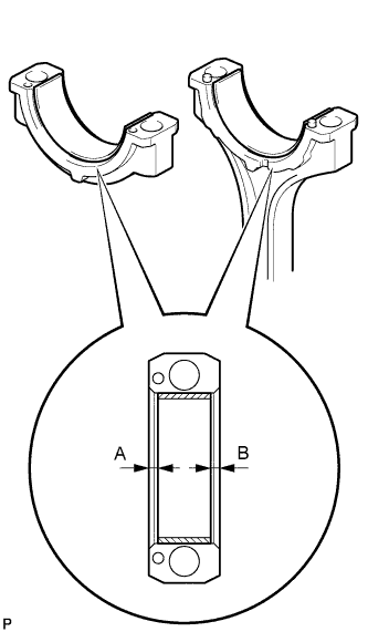 |
Using vernier calipers, measure the distance between the bearing cap's, connecting rod's and bearing's edges.
- Dimension (A, B):
- 0.7 mm (0.028 in.) or less
- ПРИМЕЧАНИЕ:
- Clean the backside of the bearing and the bearing surface of the connecting rod and bearing cap.
| 12. INSTALL PISTON SUB-ASSEMBLY WITH CONNECTING ROD |
Apply engine oil to the cylinder walls, the pistons, and the surfaces of the connecting rod bearings.
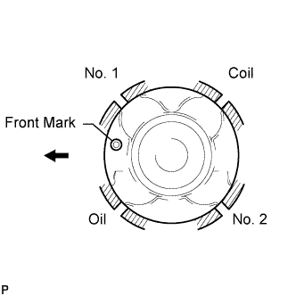
Position the piston rings so that the ring ends are as shown in the illustration.
- ПРИМЕЧАНИЕ:
- Do not align the ring ends.
 |
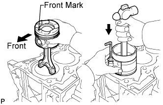
Using a piston ring compressor, push the correctly numbered piston and connecting rod into the cylinder with the front mark of the piston facing forward.
- ПРИМЕЧАНИЕ:
- Match the numbered connecting rod cap with the connecting rod.
 |
Align the matchmarks of the connecting rod cap and connecting rod. Install the connecting rod cap with the front mark facing forward.
 |
Apply a light coat of engine oil to the threads and under the heads of the connecting rod cap bolts.
Install the connecting rod cap bolts.
- УКАЗАНИЕ:
- The connecting rod cap bolts are tightened in 2 progressive steps.
- If any connecting rod bolt is broken or deformed, replace it.
Install and alternately tighten the bolts of the connecting rod caps in several steps.
- Момент затяжки:
- 40 Н*м{408 кгс*см, 30 фунт-сила-футов}
- УКАЗАНИЕ:
- If a cap bolt does not meet the torque specification, replace the connecting rod cap bolts.
Mark the front side of each connecting cap bolt with paint.
Retighten the cap bolts by 90° as shown.
Check that the painted marks are now at a 90° angle to the front.
Check that the crankshaft turns smoothly.
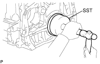
| 13. INSTALL ENGINE REAR OIL SEAL |
Using SST, tap in a new oil seal until its surface is slightly lower than the edges of the cylinder block and crankshaft bearing cap.
- SST
- 09223-56010
- ПРИМЕЧАНИЕ:
- Keep the lip free from foreign matter.
- Do not tap the oil seal at an angle.
- Make sure that the oil seal surface does not protrude beyond the edges of the cylinder block and bearing cap. It is acceptable if the oil seal surface is flush with the edges of the cylinder block and bearing cap.
 |